Using Linrad on microwaves... it can help
0. Introduction.
My Linrad setup sort of works. I am currently experimenting and trying to understand all of this exiting stuff...
I only use Linrad for 23cm+ tropo/RS/AS/... operating. My setup is
simple. The microwave transverters are DB6NT, with GPS locked G8ACE
OCXOs. This gives good frequency stability. Still we need better tools
to decode and to see what is happening on the microwaves, I try to use
Linrad to achieve this. I guess on microwaves we don t need a lot of
dynamic range aso... basic stuff can help us quite a lot.
1. Description.
Home station
I use a Delta 44 sound card on a dell MT 530 Precision (dual 2G Xeon, 2Gb RAM - boy are these cheap on Ebay) running Debian. This seems more than adequate. Linrad version is the W3SZ xlinrad package.
The 144MHz is mixed to 28MHz using an old 2m converter preceded by a variable gain amplifier. I use a modified (see below) ESS Time Machine as a baseband transverter with LO daughterboard driven by a tunable LO. The tunable LO is the ESS Flash Crystal.
I like this agile LO, it is cheap, has nice PC (RS-232) control and is
very compact. It is based on my favorite LMX2306 PLL wth a discrete VCO
and driven by 10MHz. I have tried both the HP and PTS lab synthesizers
and have not found a lot of difference.
Portable station
Baseband transverter: Softrock v7.0
2. Findings.
Here is an example of how Linrad can look during a tropo opening. Imagine how nice it is pointing at the RS cloud on 3cm.
I was not able to copy all beacons... too little time! But all the rest
was just point-and-click receiving, Linrad does all the work.
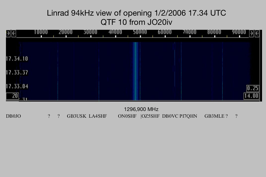
Fig: Linrad waterfall display of JO20iv opening looking N.
3. Time machine.
I use a very simple RX converter and a Time Machine. The noise
performance of the Time Machine can be improved drastically by making
the changes indicated by Leif on the mailing list (see below).
Fantastic improvement for the LF noise in my system.
Fig: "before" and "after" modifications to the Time Machine - the beacons GB3MHL (1296,830) and GB3USK (1296,870) are visible.
Here is Leifs Email (I have only implemented the "red" lines at this time).
10/20/06 7:35 PM
Leif Asbrink

Have a look at the schematic diagram here:
http://www.expandedspectrumsystems.com/prod2.html

In early versions C8 and C11 were far too small (0.1 uF I think)
Check that they are big electrolytic capacitors.

If I were responsible for the design I would break the DC
connection between the output ground and the power supply
as well as between the output ground and the RF input ground.

One way would be to connect J3, pin1 with wires to all of the
ground points of the AF circuitry so all of them would be
separated from the ground points of J1 and J5.

It means the groundings of U1,U2, R5, R7, C10, C22, R4,R13
and C11. Then connect a 1k resistor from the J3 ground to the
J1/J5 ground.

There will be a need to connect the U1 and U2 grounds to the
J1/J5 ground with decoupling capacitors to leave the RF current
path unchanged around the mixers. The U3 and U4 ground points
have to stay connected to the J1/J5 ground since they carry
DC currents.

It may be a good idea to reduce the coupling and decoupling
capacitors C14, C20, C25, C26 and C12 to 10nF and use the same
value for the new decouplers at U1 and U2. The sum of all these
capacitors should have a high impedance at the frequency of
the LF noise.

                       ---   o   ---

Rather than modifying the unit you might try to operate it from
a battery with nothing connected to the RF input (or any other
point on the unit).

This is an experiment: Just a single cable must be allowed.
>From the Time Machine to the soundcard with a battery to supply
DC. You should then not see any LF noise:-) If you do, the reason
has to be pick-up of magnetic field or perhaps, but less likely
pick-up of electric field. Wrap the board plus battery in plastic
foil and then wrap household aluminium foil around and connect
the aluminium foil to a wire that goes to any ground point of the
Time machine. This will eliminate electric fields completely.
If something is left it is magnetic. Then move the unit around
and you will soon know the source of the magnetic field......

If you can not move the source of the magnetic field away you
can get rid of it with thick copper (3 mm or more) and/or
transformer steel. (Junk a big transformer to get the material)

                       ---   o   ---

I would guess that you will not see any pick-up of either electric
or magnetic fields. There will just be a nice-looking noise floor
when you operate from a battery without any input signal.

If you then connect the 8012A you will most probably get the
LF noise back. You can then connect the 8012A through an RF
transformer and do the calibration. Maybe you will want
to use a transformer always..... (Easier than rebuilding the
unit)

Finally when the unit is calibrated and operates without AF
noise in your system from a battery you might find that the
12 V power supply can not be used without getting the AF noise
back.

There are two different mechanisms that both can be cured fairly
easily:

1) Ground currents. Make sure that the 12V supply is floating
with respect to every other ground point. Then route the 12V
DC line to the PC and connect its ground to the ground of the
soundcard (use a d-sub screw) Then route the 12 line parallel
to the audio cable (twisted is fine) up to the Time Machine.

2) Inadequate filtering. Just put a big electrolytic capacitor
on the output of the supply. 10000uF perhaps.


All the above assumes that the Time Machine has its own 12V supply.
Surely you can use a common supply, but then you have to think
carefully where the ground loops are and what current they carry.

With the re-design suggested at the beginning ground loops and
AF noise carried by them would not enter the soundcard.

WARNING. I have not tested the modification (I have no
Time Machine) but I do think it would work fine. If you
destroy a board testing it without sucess I take no
responsibility.


By the way, I think R7 and R5 should be connected in series
with C19 and C21 and not to ground. Then there should be
capacitors parallel to R13 and R4. This way the RF components
would still see 150 ohms to ground (50 ohms would be better)
while the audio output would be loaded by 500 ohms. The advantage
would be that the MAX410 would not be loaded with very strong
RF signals (at RF+LO) It can produce no more than 4.5 V/us
at the output so RF signals easily cause intermodulation
that appears in the audio output.
back
ON4IY on4iy@qsl.net -- 2/2/2006