MORE ABOUT OBLONGS 1
Inspired by the article „Oblong Antennas for VHF“ in Dubus 3/2007, and dissapointed with relatively poor results, I have designed several “wings” of oblongs, for 144, 432 and 1296 MHz, up to 61 elements.
My experience says there are no better antenna types then yagi. This article is not to confirm such a statement, but...
There is one thing, at least, which makes oblong a very interesting antenna.
If you take an optimized yagi antenna, and change its elements diameter from, for example, 5 mm to 5.5 mm, such an antenna is for scrap. But, if you take an oblong and change its diameter from 5 to 10 mm, such an antenna will still be usable.
That means the oblong is very insensitive to construction errors and to surrounding condition. Better to say, it is more expectable to obtain what is designed in reality. But, designing oblong antennas is much more difficult than for yagis. First, many more segments must be used for modelling, and this makes your PC slow down. The biggest problem is low impedance for quads and oblongs. The ratio between element height and width can be changed and, accordingly, the best ratio between impedance and other parameters can be defined
My good friend Andra, YU1QT, gave some models in the article mentioned above. The conclusion of this article was: high side lobs, not easy to build, poor gain in comparison with yagis; in other words: there seemed to be no reason to build and to use such an antenna.
YU1QT made some omissions, though, because he did not “tweak” his models.
Nowadays, many computer programs are available for antenna modelling. Some of them are very useful and free. 4NEC2 by Arie Voors, www.http://home.ict.nl/~arivoors/ is probably the best. Also good (and even better) is EZNEC www.eznec.com/ by W7EL, but this is professional and expensive software, though its core is based on the same NEC2 engine.
I am using 4NEC2, as YU1QT did. 4NEC2 has its optimizer but it is not quite friendly with oblongs. You have to put the optimizer to work and, after it has finished, you must “tweak” the obtained results by your own hands and brain. Without tweaking, you will get antenna as given in Andra’s article. Such additional work is really hard, but it is usually well rewarded, because you can normally get 0,5 dB more gain, and several dBs more side lobe suppression.
I performed this additional work by searching for best G/T ratio. That means, you have to make a small change in antenna dimensions, than to check response in terms of G/T, and adopt the change if G/T improves. For G/T calculations, I am using TANT, a small DOS program made by YT1NT (VA3TTN) http://www.geocities.com/va3ttn/Tant.zip. It is quite a tiring job, because hundreds of calculations have to be made. Therefore I deeply recommend Arie to implement an automatic “search for best G/T” calculation in his 4NEC2 optimizer; that action would make modeling much better and easier.
Now I want to give one oblong antenna design for 1296 MHz. If interested in other designs, please, send an e-mail request to yu7xl@nadlanu.com.
Super oblong for 1296 mhz
I have found that smaller diameter of wires gives better results with oblongs. The answer is, maybe, that smaller dia brings higher value of impedanse. Anyway, this can be well used on UHF bands.
Silverplated copper wire of 1 and 1,5 mm diameter is used in my simulations. It is very suitable for manipulation (cutting, bending, soldering...), resistant against corrosion and, finally, has the best conductivity, meaning minimum losses. The wire is cheap and easy to find.
All elements have to be mounted insulated over the boom. If the elements are at least 10 mm apart of the boom surface, the diameter of the boom is not very important.
I have designed several tens of oblong antennas for 1296 MHz. Here described is the biggest one, consisting of 61 elements and giving excellent performances. Its boom length is nearly 6,00 metres!
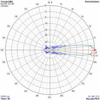
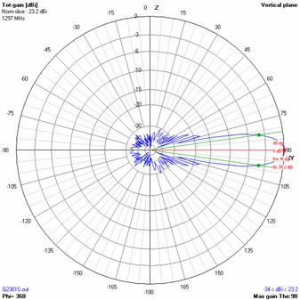
According to simulations, you can expect the following: gain of 23,20 dBi, F/B of 35,20 dB. Side lobes are suppressed 20 dB in the horizontal and 19,7 dB in the vertical plane. The main lobe is 13,6 x 13,8 degrees wide. The total antenna temperature (without losses) is 19,8◦K and G/T +10,23 dB. A bandwidth of 17 MHz can be expected for SWR better than 1,5, and the impedance at the central frequency of 1296,9 MHz is exactly 50±j0 Ohms. You will nowhere see such a clean and sharp pattern as here, for this antenna!
This antenna is just being built by YT1WV and will be ready for the next VHF/UHF season. All antennas designed in 4NEC2, gave the expected performances when checked in practice, so there is no reason not to start building this antenna now.
Antenna Q2361S for 1296 MHz – by YU7XL
Performances:
|
TYPE |
ELE |
L (mm) |
G (dBi) |
F/B (dB) |
F/Sh (dBi) |
F/Sv (dBi) |
Hor (◦) |
Ver (◦) |
Temp (◦K) |
G/T (dB) |
ΔF * (MHz) |
|
Q2361S |
61 |
5957 |
23,20 |
35,20 |
20,09 |
19,66 |
13,6 |
13,8 |
19,8 |
+10,23 |
17,2 |
* ΔF given for SWR=1,5
Dimensions:
|
|
Ref |
De |
D1 |
D2 |
D3 |
D4 |
D5 |
D6 |
D7 |
D8 |
D9 |
D10 |
D11 |
D12 |
|
Pos |
0 |
52 |
96 |
175 |
263 |
354 |
456 |
552 |
656 |
759 |
865 |
974 |
1083 |
1194 |
|
Length |
102,0 |
94,0 |
90,0 |
86,0 |
84,0 |
81,0 |
80 |
79,0 |
78,0 |
77,0 |
75,0 |
75,0 |
74,0 |
74,0 |
|
|
D13 |
D14 |
D15 |
D16 |
D17 |
D18 |
D19 |
D20 |
D21 |
D22 |
D23 |
D24 |
D25 |
D26 |
|
Pos |
1301 |
1407 |
1516 |
1627 |
1741 |
1850 |
1957 |
2063 |
2172 |
2275 |
2386 |
2481 |
2578 |
2675 |
|
Length |
74,0 |
74,0 |
72,0 |
72,0 |
72,0 |
72,0 |
72,0 |
72,0 |
72,0 |
71,0 |
71,0 |
70,0 |
70,0 |
70,0 |
|
|
D27 |
D28 |
D29 |
D30 |
D31 |
D32 |
D33 |
D34 |
D35 |
D36 |
D37 |
D38 |
D39 |
D40 |
|
Pos |
2769 |
2874 |
2971 |
3084 |
3182 |
3277 |
3377 |
3467 |
3562 |
3657 |
3759 |
3861 |
3959 |
4058 |
|
Length |
69,0 |
69,0 |
69,0 |
69,0 |
68,0 |
68,0 |
68,0 |
68,0 |
68,0 |
68,0 |
68,0 |
68,0 |
68,0 |
68,0 |
|
|
D41 |
D42 |
D43 |
D44 |
D45 |
D46 |
D47 |
D48 |
D49 |
D50 |
D51 |
D52 |
D53 |
D54 |
|
Pos |
4156 |
4258 |
4355 |
4459 |
4561 |
4662 |
4763 |
4851 |
4951 |
5051 |
5152 |
5255 |
5357 |
5458 |
|
Length |
67,0 |
67,0 |
67,0 |
67,0 |
67,0 |
67,0 |
67,0 |
67,0 |
67,0 |
67,0 |
67,0 |
67,0 |
67,0 |
67,0 |
|
|
D55 |
D56 |
D57 |
D58 |
D59 |
REMARKS: : - All elements made of silverplated wire Ǿ1 mm - The height of all rectangles is 19 mm - All dimensions given in milimetres |
|
Pos |
5569 |
5671 |
5771 |
5871 |
5957 |
|
|
Length |
67,0 |
67,0 |
67,0 |
67,0 |
67,0 |
Diagrams:
Fig. 2: 61 element oblong for 23 cm – horizontal plane (top) and vertical plane (bottom)
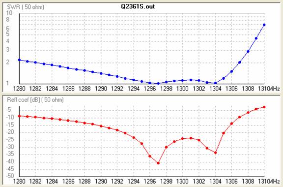
Fig. 1: SWR (top) and refl. coef. (bottom) for the 61 ele oblong antenna (4NEC2 simulation)
Editor: A re-simulation of the antenna with the provided dimensions by YU7EF with EZNEC showed the following results: gain 23.06 dBi, F/B 34.8 db There is about 0.16 db less in gain than in the 4NEC2 simulation because YU7XL did not consider the internal loss of the aantenna material. Anyway, the good pattern and performance data were confirmed in general.
YU7EF comments: For comparison this antenna was simulated by YU7EF with different materials for the elements: with no loss, 23.19 dB, silver 23.06 dB, copper 23.05 dB, aluminium 22.98 dB, stainless steel 22.28 dBi. This design is realy good or I should say results are remarkable, even with loss included. Again, there is only the question of building it with such a good precision to maintain the specifications. Since this a 23 cm antenna it might be possible to have it in reality, but this a very long antenna which will require at least a 30 x 30 mm boom. Even if the elements are spaced 10 mm above the boom, the question id if they would be influenced by such a large boom, or if it would be required to introduce a boom correction.