MORE ABOUT OBLONGS 4
A challenging antenna for 144 MHz
It has recently become lnown that a 2 and 3-element quad has higher gain than 2 or 3-element yagi. As the boom length and the number of elements are increased, the difference becomes more and more negligible. This is true according to my own experience, but only up to a boom length of approximately 5 WL You can see that comparing my oblong models with yagis designed by YU7EF. With shorter booms, oblongs are much better than yagies. Than, the difference between my 14-element oblong and the EF 14-element yagi with the same boom length is small. The oblong is still beter, but not by much.
Now here is a big surprise:
When the boom length is increased to more than 5 WL, things change rapidly. It seems that the waveguide effect comes into play, and the longer oblong antenna becomes the much better it becomes. Every additional director is almost same in length as the previous one, and gives more gain, with no significant influence to the front-to-back and front-to-side ratios.
It is a pity that a 5 or 10 WL (or even more) antenna length is quite difficult to build on the 144 MHz band. One can try it! I know some EME operators who use a single antenna for EME operation, which is 17 or 18 metres long. The antenna gain for such a length is 18 to 20 dBi, which can be easily achieved with 4 stacked shorter antennas. But, when stacked, you have to count on additional losses in splitters, connectors and phasing lines and, finally, the antenna pattern becomes very poor. Using a single long antenna, all performances remain good.
Anyway, this fact makes oblong very useful on the 432 and 1296 MHz bands, where the boom length of 10, even 20 WL, is quite common. Therefore, I can state that the quad (oblong) is a true UHF antenna, much better than a yagi.
An oblong usually has a bigger bandwidth than yagi. Whrn increasing the yagi boom length, its bandwidth becomes lower and lower. When increasing the oblong length, its bandwidth becomes bigger and bigger! The gain becomes higher and higher, and the temperature lower and lower!
Now I want to present my biggest challenge for a brave VHF enthusiast: the 25 element, almost 20 meters long oblong antenna for the 144 MHz band. Maybe there is a ham who can dare to build this antenna? If so, please, send me (and Dubus) details of how this antenna realy works.
Anyway, this article must be interesting to everyone, just to show what happens with extremly long oblongs.
25 ELEMENT OBLONG ANTENNA Q225D1XL
Performance Data: (No loss condition)
|
TYPE |
ELE |
L (mm) |
G (dBi) |
F/B (dB) |
F/Sh (dBi) |
F/Sv (dBi) |
Hor (◦) |
Ver (◦) |
Temp (◦K) |
G/T (dB) |
ΔF * (kHz) |
|
Q225D1XL |
25 |
19519 |
19,69 |
32,67 |
18,99 |
17,97 |
20,6 |
21,0 |
213,2 |
-3,62 |
2,600 |
* ΔF given for SWR=1,5 (from 143.500 to 146.100 MHz)
Performance Data: (losses included)
|
Element material |
G (dBi) |
Temp (◦K) |
G/T (dB) |
|
Aluminum rods |
19,56 |
215,3 |
-3,77 |
Dimensions:
|
|
Ref |
De |
D1 |
D2 |
D3 |
D4 |
D5 |
D6 |
D7 |
D8 |
D9 |
D10 |
D11 |
|
|
Pos |
0 |
275 |
480 |
862 |
1489 |
2189 |
2973 |
3805 |
4678 |
5597 |
6528 |
7455 |
8387 |
|
|
Length |
786 |
734 |
708 |
691 |
673 |
659 |
645 |
633 |
625 |
611 |
609 |
605 |
597 |
|
|
|
D12 |
D13 |
D14 |
D15 |
D16 |
D17 |
D18 |
D19 |
D20 |
D21 |
D22 |
D23 |
|
|
|
Pos |
9318 |
10271 |
11205 |
12175 |
13135 |
14065 |
15065 |
15975 |
16895 |
17855 |
18745 |
19519 |
|
|
|
Length |
594 |
588 |
578 |
576 |
564 |
564 |
562 |
562 |
560 |
560 |
558 |
558 |
|
|
|
REMARKS: : - All elements are made of Al rods Ǿ5 mm - The height of all rectangles is 320 mm - All dimensions given in milimetres |
||||||||||||||
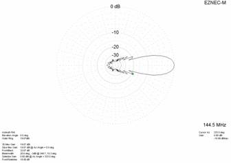
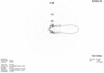
Diagrams (No losses included)
Fig. 1: 25 element Oblong for 2m – horizontal plane (left) and vertical pkane (right)
(EZNEC simulation – losses not included)
Diagrams (Losses included)
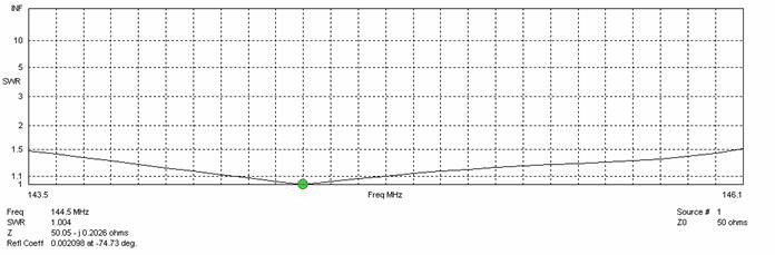
Fig. 2: SWR sweep for the 25 ele 2m oblong antenna (EZNEC simulation, losses included)