HYBRID LFA YAGI OBLONG ANTENNAS
Is there anyone who did not hear IK3MAC via EME? Well, his 24x23 ele monster antenna system for 144 MHz does the job! There are a few photos of his antenna system available on Internet. You can see that the antennas are a combination of yagi and loop elements but no details are available. I started investigating the secret.
My first step was to take EZNEC files of some good yagi designs and to convert them into the hybrid antennas and look at the simulations. I chose some of my 200 Ohms LFA yagis and also some of YU7EF yagis converted to LFA. First, with only the last director changed, a better gain and G/T was achieved. The feed impedance remained at 200 Ohms. Every subsequent director converted gave better and better results. Well, not quite! When the conversion process got to the elements close to the radiator, the antenna loss temperature started to increase, and despite the fact that the gain was a bit higher, the overall G/T ratio decreased. At the same time, the impedance became unacceptable, so some changes in element position have to be made, which made the G/T even worse.
The best solution I found was to keep the reflector, radiator and first two to five directors as yagi elements. and change the rest to loop elements.
And...this is just what the IK3MAC design approximately looks like! The antenna outperforms all existing ordinary yagi or loop antennas!
I do not know if Graziano will publish his design. I have found the rectangle with a width/height ratio = 1 gave the best results. This ratio gives an additional benefit, as you will see later. Probably, the IK3MAC round loop is still better, but for me it is practicaly impossible to make round model for EZNEC.
I have to say that I have modelled several antennas for 50 Ohms feed impedance. The performance achieved was not as good as for 200 Ohm. Therefore, all my models unless otherwise stated, are designed for 200 Ohm impedance, and the feed point is at DE2. That means that a ½ WL coaxial balun is required for matching and balancing.
Here are two of my most successful hybrid models:
ANTENNA QY21105XL4
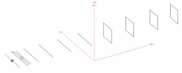
This antenna consists of 7 yagi and 4 oblong elements, made of Al rods 5mm diameter:
Fig 1: QY21105XL4
Performance
|
ANTENNA TYPE |
No of ele |
Length (mm) |
Gain (dBi) |
F/B (dB) |
F/Sh (dB) |
F/Sv (dB) |
H lobe (◦) |
V lobe (◦) |
TA (◦K)* |
G/T (dB)* |
Central f (MHz) |
Δf for SWR=1,5 |
|
|
Lower |
Upper |
||||||||||||
|
QY21105 XL4 |
11 |
6000 |
15,43 |
28,34 |
18,92 |
18,26 |
33,2 |
35,6 |
220,4 |
-8,00 |
144,500 |
143,200 |
146,100 |
|
15,33 |
28,22 |
18,90 |
18,25 |
33,2 |
35,6 |
222,5 |
-8,14 |
||||||
Table 1 - The first row gives free space data with no losses, the lower row gives data with losses for aluminum included.
Comparison table
|
Type |
Length (mm) |
Gain (dBi) |
TA |
G/T |
Freq (MHz) for SWR=1,5 |
|
QY21105XL4 |
6000 |
15,43 |
220,4 |
-8,00 |
143,200 – 146,100 |
|
15,33 |
222,5 |
-8,14 |
|||
|
EF0211B-5 |
5980 |
15,13 |
229,1 |
-8,47 |
140,600 – 145,210 |
|
15,03 |
230,8 |
-8,60 |
|||
|
G0KSC 12ELKKA |
6048 |
15,22 |
228,7 |
-8,37 |
142,500 – 145,470 |
|
15,14 |
229,8 |
-8,47 |
Table 2 - The first row gives free space data with no losses, the lower row gives data with losses for aluminum included.
Dimensions
|
|
RE |
DE1 |
DE2 |
D1 |
D2 |
D3 |
D4 |
D5 |
DQ1 |
DQ2 |
DQ3 |
DQ4 |
|
Position |
0 |
265 |
345 |
415 |
705 |
1250 |
1934 |
2695 |
3535 |
4355 |
5245 |
6000 |
|
Length |
1018 |
1018 |
850 |
946 |
958 |
932 |
916 |
900 |
522 |
500 |
492 |
476 |
Table 3 - All elements made of Alu rods Ø5 mm. The height of oblong elements 500 mm. No boom correction included
As you can see, the reflector and the first four directors are yagi elements. The directors DQ1 to DQ4 are oblong elements, 500 mm high, and their horizontal sides are given in the table. Material for all elements is 5 mm diameter aluminium rod.
Simulation results
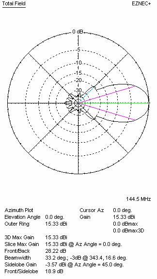
a) no loss condition
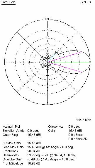
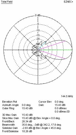
b) losses included for aluminum)

|
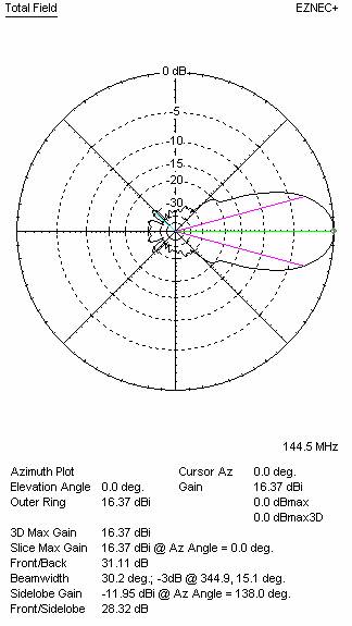
Fig. 3: Azimuth plot QY21105XL4 |
Fig. 4: Elevation plot QY21105XL4 |
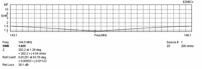
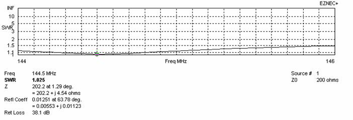
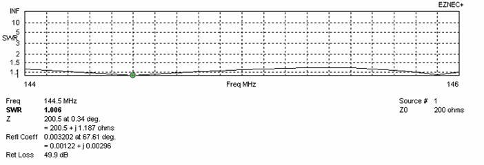
Fig. 5: SWR plots QY21105XL4 (simulation)
ANTENNA QY21308XL4
This antenna consists of 7 yagi and 6 oblong elements, all made from 8 mm diameter Al tube:
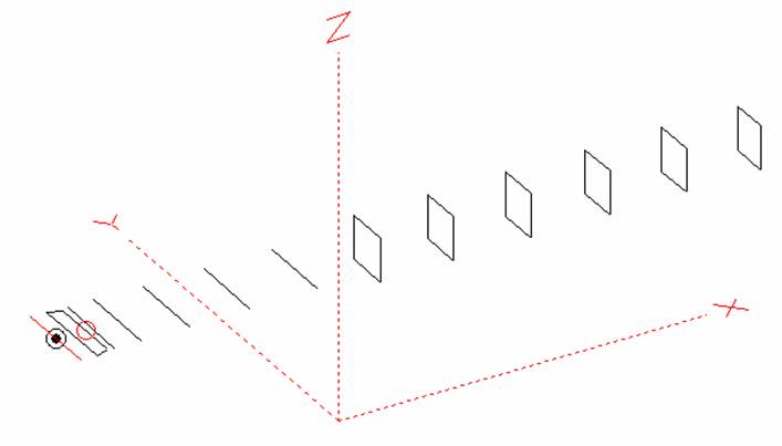
Fig. 6: QY21308XL4 layout
Performance
|
ANTENNA TYPE |
No of ele |
Length (mm) |
Gain (dBi) |
F/B (dB) |
F/Sh (dB) |
F/Sv (dB) |
H lobe (◦) |
V lobe (◦) |
TA (◦K)* |
G/T (dB)* |
Central f (MHz) |
Δf for SWR=1,5 |
|
|
Lower |
Upper |
||||||||||||
|
QY21308XL4 |
13 |
7845 |
16,37 |
31,11 |
28,32 |
18,39 |
30,2 |
31,4 |
217,7 |
-7,01 |
144,500 |
143,200 |
146,200 |
|
16,28 |
31,43 |
28,29 |
18,38 |
30,2 |
31,2 |
219,5 |
-7,14 |
||||||
Table 4 -The first row gives free space data with no losses, the lower row gives data with aluminium losses included.
Comparison table
|
Type |
Length (mm) |
Gain (dBi) |
TA (K) |
G/T (dB) |
Freq (MHz) for SWR=1,5 |
|
QY21308XL4 |
7845 |
16,37 |
217,7 |
-7,01 |
143,200 – 146,200 |
|
16,28 |
219,5 |
-7,14 |
|||
|
G0KSC 13ELKKB |
7855 |
16,13 |
229,1 |
-7,28 |
142,650 – 145,370 |
|
16,03 |
221,1 |
-7,42 |
|||
|
EF0213-5 |
8155 |
16,40 |
224,8 |
-7,12 |
143,660 – 144,620 |
|
16,25 |
227,6 |
-7,32 |
Table 5 - The first row gives free space data with no losses, the lower row gives data with aluminium losses included.
Dimensions
|
|
RE |
DE1 |
DE2 |
D1 |
D2 |
D3 |
D4 |
D5 |
DQ1 |
DQ2 |
DQ3 |
DQ4 |
DQ5 |
DQ6 |
|
Position |
0 |
180 |
330 |
401 |
705 |
1251 |
1938 |
2705 |
3525 |
4355 |
5233 |
6128 |
6995 |
7845 |
|
Length |
1012 |
990 |
868 |
942 |
951 |
925 |
907 |
887 |
526 |
504 |
496 |
486 |
476 |
456 |
Table 6 - All elements made of Ø8 mm Al rod. The height of oblong elements 500 mm. No boom correction included
Simulation results
a) no loss condition)
b) Aluminium losses taken into account
|
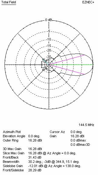
Fig. 7: Azimuth plot QY21308XL4 |
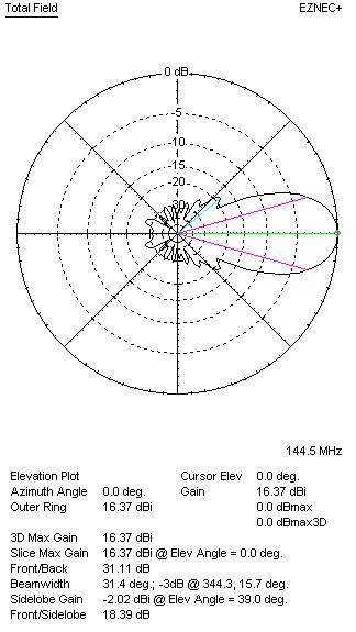
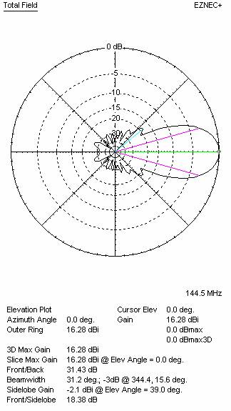
Fig. 8: Elevation plot QY21308XL4 |
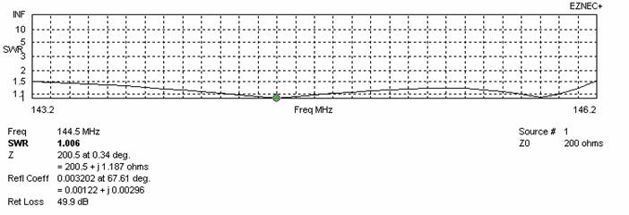
|
Fig. 9 – SWR plots QY21308XL4 (simulation) |
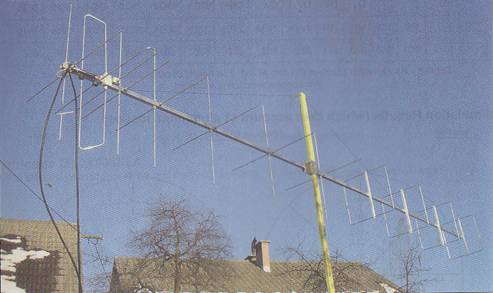
Fig. 10: QY21105XL4 built by S52FO
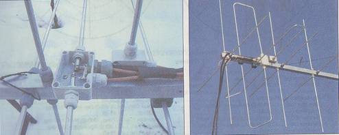
Fig. 11 & 12: Details of the driven elements