ANTENNA X23005XL1Q
PERFORMANCES:
|
No of ele |
L (mm) |
G (dBi) |
F/B (dB) |
F/Sh (dBi) |
F/Sv (dBi) |
Hor (◦) |
Ver (◦) |
Temp (◦K) |
G/T (dB) |
Tlos (K) |
|
30 |
9065 |
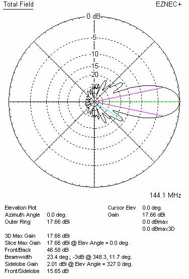
17.71 |
46.58 |
16.10 |
15.65 |
27.0 |
23.4 |
221.5 |
-5.74 |
5.4 |
WORKING CONDITION:
|
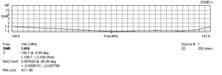
Frequency for SWR=1.5 (MHz) |
Z (Ώ) at 144.100 MHz |
SWR at 145.000 MHz |
||
|
Lowest |
Highest |
Bandwidth |
||
|
140.600 |
147.800 |
7.200 |
197.7 |
1.08:1 |
DIMENSIONS:
|
|
Ref |
De |
D1 |
D2 |
D3 |
D4 |
D5 |
D6 |
D7 |
D8 |
D9 |
D10 |
D11 |
D12 |
D13 |
D14 |
|
Pos |
0 |
365 |
528 |
938 |
1431 |
1732 |
2276 |
3022 |
3756 |
4528 |
5302 |
6078 |
6832 |
7622 |
8394 |
9065 |
|
Length |
1014 |
786 |
931 |
927 |
897 |
873 |
897 |
893 |
889 |
885 |
879 |
877 |
875 |
875 |
869 |
849 |
|
Height |
0 |
±240 |
±180 |
±330 |
±440 |
±510 |
±570 |
±650 |
±725 |
±785 |
±805 |
±815 |
±815 |
±815 |
±795 |
±755 |
|
Dimensions given in milimetres - Diameter of elements 5 milimetres - No boom correction included. |
||||||||||||||||
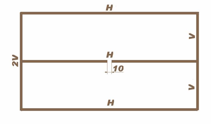
CONSTRUCTION OF RADIATOR
H = 786
V = 240
Ø= 5 mm
COMPARISON (inserted in a part of VE7BQH table, where it belongs according to its boom length)
|
TYPE OF ANTENNA |
SINGLE ANTENA |
FOUR ANTENNAS IN H-STACK |
||||||||
|
L (λ) |
GAIN (dBd) |
Z (ohms) |
VSWR Bandwidth |
E (m) |
H (m) |
Ga (dBd) |
Tlos (K) |
Ta (K) |
G/T (dB) |
|
|
G0KSC 14 LFA |
4.30 |
14.51 |
47.1 |
1.22:1 |
4.24 |
4.02 |
20.41 |
5.5 |
218.1 |
-0.82 |
|
KF2YN Boxkite 16 |
4.30 |
15.85 |
50.5 |
1.16:1 |
5.50 |
5.10 |
21.83 |
6.2 |
227.4 |
0.41 |
|
InnoV 14 LFA |
4.32 |
14.45 |
48.6 |
1.10:1 |
4.18 |
3.97 |
20.34 |
6.6 |
215.6 |
-0.85 |
|
X23005XL1Q |
4.35 |
15.36 |
197.7 |
1.08:1 |
4.90 |
5.70 |
21.65 |
5.4 |
214.1 |
+0.49 |
|
YU7EF 14 |
4.37 |
14.48 |
41.0 |
2.30:1 |
4.21 |
4.00 |
20.33 |
8.8 |
220.0 |
-0.94 |
|
YU7EF 14LT |
4.37 |
13.91 |
47.8 |
1.29:1 |
3.89 |
3.64 |
19.60 |
11.7 |
211.0 |
-1.49 |
|
K1FO 17 |
4.40 |
14.44 |
27.7 |
1.25:1 |
4.24 |
4.02 |
20.34 |
4.9 |
229.5 |
-1.12 |
|
DJ9BV 4.4 |
4.41 |
14.32 |
38.3 |
1.36:1 |
4.27 |
4.07 |
20.18 |
6.6 |
251.5 |
-1.68 |
|
SHARK 20 |
4.47 |
14.34 |
42.8 |
1.05:1 |
4.33 |
4.10 |
20.19 |
3.9 |
258.5 |
-1.79 |
|
I0JXX 16 |
4.47 |
14.36 |
30.4 |
1.05:1 |
4.05 |
4.05 |
20.24 |
8.4 |
217.5 |
-0.98 |
|
CC17B2 |
4.49 |
14.53 |
200.1 |
1.20:1 |
4.27 |
4.07 |
20.43 |
5.9 |
228.6 |
-1.01 |
|
Z(ohms) - measured on 144.100 MHz Bandwidth – VSWR measured on 145.000 MHz |
||||||||||
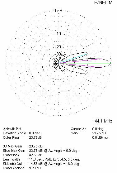
DIAGRAMS (no loss included)

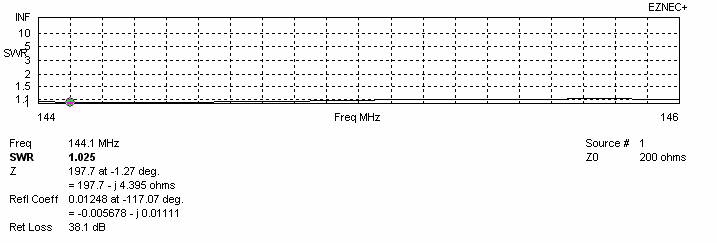
SWR DIAGRAMS (loss included for Al)
BEST DISTANCES FOR STACK
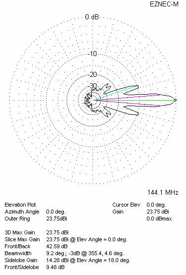
Four antennas in H-stack
|
Horizontal distance (mm) |
Vertical distance (mm) |
G (dBi) |
TA (K) |
G/T (dB) |
Tlos (K) |
Remark |
|
4456 |
5.130 |
23.60 |
216.3 |
+0.25 |
5.4 |
Per DL6WU formula |
|
4900 |
5700 |
23.80 |
214.1 |
+0.49 |
5.4 |
For max G/T |
|
4000 |
5600 |
23.55 |
213.4 |
+0.26 |
5.4 |
For lowest temperature |
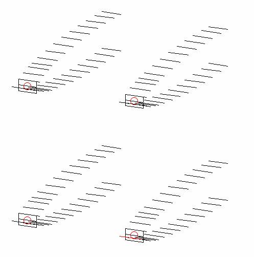
Four antennas in H-stack, H=4.90 V=5.70 metres
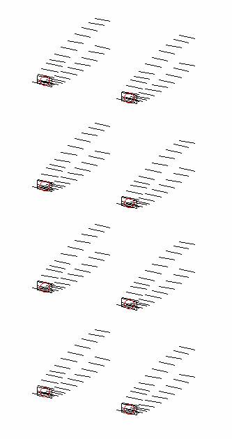
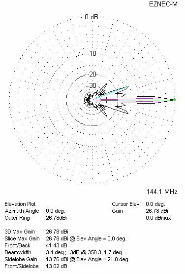
Eight antennas in stack (four in horizontal and two in vertical plane)
|
Horizontal distance (mm) |
Vertical distance (mm) |
G (dBi) |
TA (K) |
G/T (dB) |
Tlos (K) |
|
4900 |
5700 |
26.82 |
214.2 |
+3.51 |
5.4 |
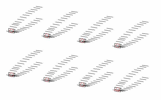
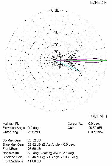
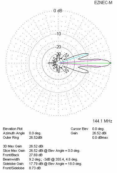
Eight antennas in stack (two in horizontal and four in vertical plane)
|
Horizontal distance (mm) |
Vertical distance (mm) |
G (dBi) |
TA (K) |
G/T (dB) |
Tlos (K) |
|
4900 |
5700 |
26.83 |
213.1 |
+3.55 |
5.4 |