ANTENNA X22006XL3Q
PERFORMANCES:
|
No of ele |
L (mm) |
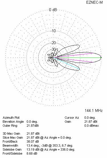
G (dBi) |
F/B (dB) |
F/Sh (dBi) |
F/Sv (dBi) |
Hor (◦) |
Ver (◦) |
Temp (◦K) |
G/T (dB) |
Tlos (K) |
|
20 |
5165 |
15.90 |
27.11 |
21.83 |
19.70 |
33.6 |
28.0 |
219.2 |
-7.51 |
5.1 |
WORKING CONDITION:
|
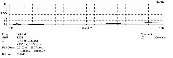
Frequency for SWR=1.5 (MHz) |
Z (Ώ) at 144.100 MHz |
SWR at 145.000 MHz |
||
|
Lowest |
Highest |
Bandwidth |
||
|
142.000 |
146.200 |
4.200 |
197.6 |
1.08:1 |
DIMENSIONS:
|
|
Ref |
De |
D1 |
D2 |
D3 |
D4 |
D5 |
D6 |
D7 |
D8 |
|
|
Pos |
0 |
345 |
529 |
924 |
1428 |
1742 |
2276 |
3032 |
3756 |
4524 |
5165 |
|
Length |
1012 |
788 |
931 |
926 |
917 |
906 |
906 |
902 |
900 |
898 |
878 |
|
Height |
0 |
±220 |
±180 |
±330 |
±450 |
±520 |
±590 |
±665 |
±725 |
±725 |
±705 |
|
Dimensions given in milimetres - Diameter of elements 6 milimetres - No boom correction included. |
|||||||||||
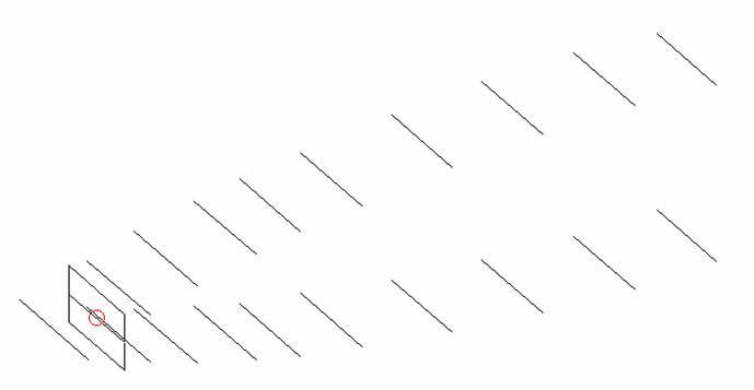
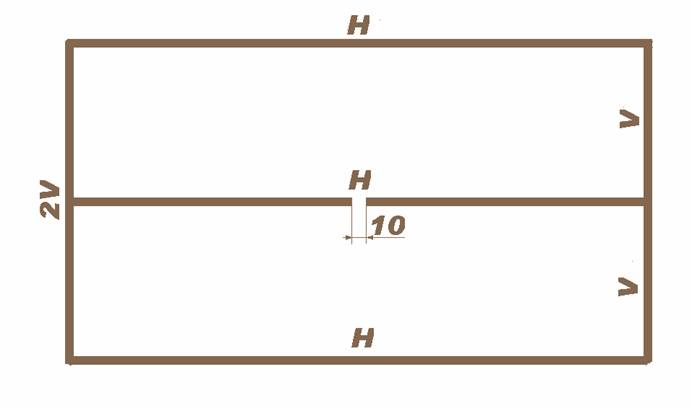
CONSTRUCTION OF RADIATOR
H = 788
V = 220
Ø= 6 mm
COMPARISON (inserted in a part of VE7BQH table, where it belongs according to its boom length)
|
TYPE OF ANTENNA |
SINGLE ANTENA |
FOUR ANTENNAS IN H-STACK |
||||||||
|
L (λ) |
GAIN (dBd) |
Z (ohms) |
VSWR Bandwidth |
E (m) |
H (m) |
Ga (dBd) |
Tlos (K) |
Ta (K) |
G/T (dB) |
|
|
DD0VF 9 |
2.46 |
12.47 |
25.0 |
1.16:1 |
3.48 |
3.18 |
18.44 |
4.4 |
235.8 |
-3.14 |
|
X22006XL3Q |
2.48 |
13.74 |
197.6 |
1.08:1 |
4.00 |
4.40 |
19.72 |
5.1 |
218.3 |
-1.52 |
|
YU7EF 10LT |
2.49 |
11.84 |
45.7 |
1.13:1 |
3.13 |
2.82 |
17.69 |
5.3 |
224.3 |
-3.67 |
|
K5GW 10 |
2.49 |
12.45 |
37.4 |
1.41:1 |
3.44 |
3.16 |
18.38 |
7.4 |
234.6 |
-3.17 |
|
G4CQM 9 |
2.52 |
12.63 |
46.4 |
2.02:1 |
3.62 |
3.35 |
18.68 |
7.3 |
244.4 |
-3.05 |
|
G0KSC 10 LFA |
2.53 |
12.61 |
48.5 |
1.05:1 |
3.48 |
3.18 |
18.54 |
2.6 |
229.8 |
-2.92 |
|
K1FO 12 |
2.53 |
12.49 |
31.1 |
1.23:1 |
3.46 |
3.18 |
18.42 |
4.3 |
240.7 |
-3.25 |
|
YU7EF 10 |
2.59 |
12.44 |
50.3 |
1.06:1 |
3.39 |
3.10 |
18.34 |
6.9 |
227.8 |
-3.08 |
|
Gulf Alpha 11 |
2.60 |
12.33 |
204.1 |
1.07:1 |
3.46 |
3.19 |
18.32 |
5.3 |
248.9 |
-3.49 |
|
Gulf Alpha 11 XPOL |
2.60 |
12.31 |
188.1 |
1.07:1 |
3.32 |
3.32 |
18.29 |
5.6 |
249.8 |
-3.53 |
|
G0KSC 10LFA+2 |
2.60 |
12.45 |
47.4 |
1.24:1 |
3.39 |
3.09 |
18.35 |
4.1 |
226.7 |
-3.06 |
|
Z(ohms) - measured on 144.100 MHz Bandwidth – VSWR measured on 145.000 MHz |
||||||||||
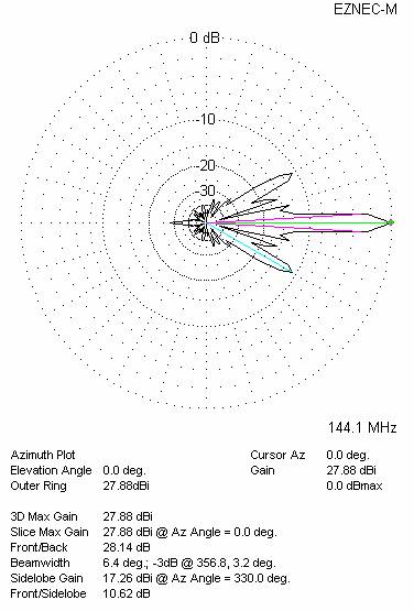
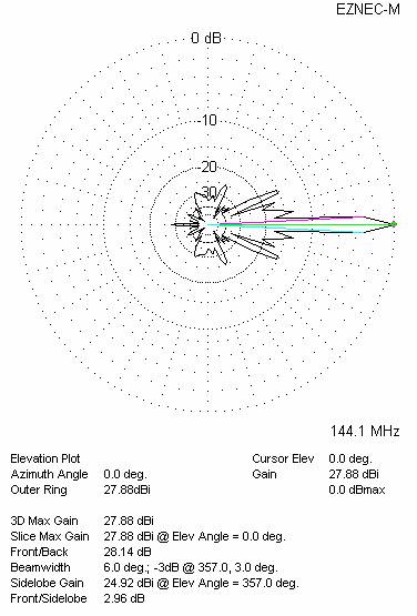
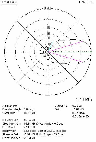
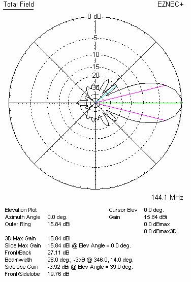
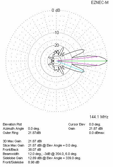
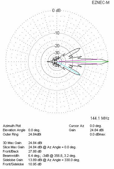
DIAGRAMS (no loss included)
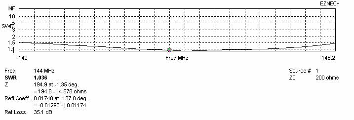
SWR DIAGRAMS (loss included for Al)
BEST DISTANCES FOR STACK
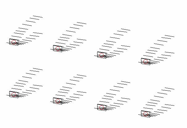
Four antennas in H-stack
|
Horizontal distance (mm) |
Vertical distance (mm) |
G (dBi) |
TA (K) |
G/T (dB) |
Tlos (K) |
Remark |
|
3599 |
4300 |
21.82 |
218.6 |
-1.58 |
5.1 |
Per DL6WU formula |
|
4000 |
4400 |
21.87 |
218.3 |
-1.52 |
5.1 |
For max G/T |
|
4000 |
4400 |
21.87 |
218.3 |
-1.52 |
5.1 |
For lowest temperature |

Four antennas in H-stack, H=4.00 V=4.60 metres
Eight antennas in stack (four in horizontal and two in vertical plane)
|
Horizontal distance (mm) |
Vertical distance (mm) |
G (dBi) |
TA (K) |
G/T (dB) |
Tlos (K) |
|
4000 |
4400 |
24.90 |
218.1 |
+1.51 |
5.1 |

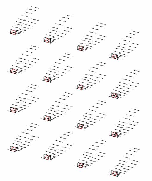
Sixteen antennas (four in horizontal and four antennas in vertical plane)
|
Horizontal distance (mm) |
Vertical distance (mm) |
G (dBi) |
TA (K) |
G/T (dB) |
Tlos (K) |
|
4000 |
4400 |
27.94 |
221.1 |
+4.49 |
5.1 |
SIXTEEN ANTENNAS AT H=4.00+4.00+4.00 AND V=4.40+4.40+4.40 METRES - DIAGRAMS