ANOTHER HYBRID ANTENNA SYSTEM FOR 432 MHZ (DUBUS 1/2016)
Slobodan Bukvic, YU7XL
http://www.qslnet.de/member/yu7xl/
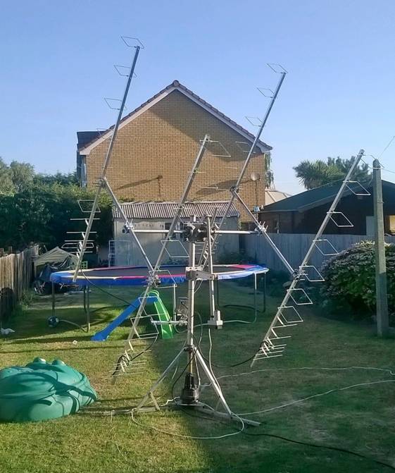
Fig. 1: 432 MHz Hybrid antenna system made by M0ABA
As stated before (1), hybrid antennas have the highest potential performance, compared with conventional yagi or loop antennas. Here is a new hybrid antenna system for the 432 MHz band. With more than 28 dBi gain, it should be a good DX investment.
This 13 ele antenna consists of one reflector, a LFA radiator and four yagi directors. The remaining seven elements are in the form of rectangular, one wavelength loops, with a common height of 170 mm. The yagi-like elements are made of 10 mm aluminium tube, but the radiator and the rectangles are of 6 mm Al tube.
The antenna is 2645 mm long. Such a length allows self-supporting mounting and gives the possibility of making dual H/V polarized arrays.
ANTENNA QY71310XL6D7
The outline of the antenna is shown in Fig 1, and table 1 gives dimensions and positions of the antenna elements.
Fig.3 shows the shape of the LFA radiator and its dimensions.
Table 2 lists performance data. Note the difference in gain between table 2 and radiation patterns in Fig.4. This is caused by the need to compensate for the EZNEC error due to the bent elements of the antenna. So, the gain shown on the patterns is reduced by the value calcukated usubg the KF2YN correction formula. The gain in the table 2 is real gain, with material losses (for aluminium) included!
All performances are calculated for the central frequency of 432.100 MHz.
Finally, Fig. 5 shows the impedance diagram for the SWR better than 1.5, and Fig. 6 is the same diagram but for the frequency range of 432.100 to 435.000 MHz.
. 
Fig. 2: Outline of the QY71310XL6D7 antenna
|
|
Ref |
De1 |
De2 |
D1 |
D2 |
D3 |
D4 |
DQ1 |
DQ2 |
DQ3 |
DQ4 |
DQ5 |
DQ6 |
DQ7 |
|
Position |
0 |
60 |
100 |
131 |
226 |
411 |
651 |
906 |
1178 |
1482 |
1792 |
2078 |
2402 |
2645 |
|
Length |
331 |
338 |
338 |
300 |
351.5 |
289 |
278 |
173 |
165 |
157 |
155 |
153 |
151 |
149 |
|
Diameter |
10 |
6 |
6 |
10 |
10 |
10 |
10 |
6 |
6 |
6 |
6 |
6 |
6 |
6 |
|
Table 1 (all dimensions in milimetres) |
||||||||||||||

Fig. 3 – Sketch of the LFA radiator
|
G (dBi) |
F/B (dB) |
F/Sh (dB) |
F/Sv (dB) |
Hor (◦) |
Ver (◦) |
Temp (K) |
Tlos (K) |
G/T (dB) |
Bandwidth for SWR 1.5 (MHz) |
|
16.09 |
33.88 |
23.74 |
17.87 |
31.4 |
32.4 |
29.6 |
3.2 |
+1.38 |
422.000 – 438.100 |
Table 2 – Performance of the antenna by EZNEC, corrected by KF2YN correction formula


Fig. 4: Radiation patterns in H and V planes
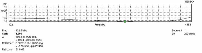
Fig. 5: Impedance diagram for SWR better than 1.5
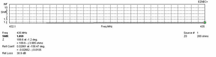
Fig. 6: Impedance diagram from 432.1 to 435 MHz
STACKING
FOUR ANTENNAS QY71310XL6D7 IN H-STACK (H=144 cm, V=1.62 cm)
|
G (dBi) |
Hor (◦) |
Ver (◦) |
Temp (K) |
Tlos (K) |
G/T (dB) |
|
22.18 |
12.6 |
11.6 |
28.7 |
3.2 |
+7.60 |
Table 3 – Performances of the four antennas in H-stack, corrected by KF2YN correction formula
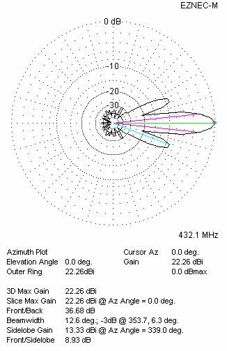
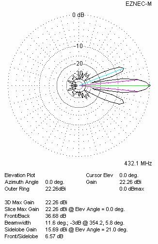
Fig. 7: Radiation patterns in H and V planes for four antennas in H-stack
SIXTEEN ANTENNAS QY71310XL6D7 IN STACK (H=144+144+144 cm, V=144+144+144 cm)
These vertical distances do not give the best G/T figure, and should be used when there is not enough space, and when both H/V polarizations are employed.
|
G (dBi) |
Hor (◦) |
Ver (◦) |
Temp (K) |
Tlos (K) |
G/T (dB) |
|
28.21 |
6.0 |
5.0 |
30.4 |
3.2 |
+13.38 |
Table 4 – Performances of the sixteen antennas at minimum stacking, corrected by the KF2YN correction formula

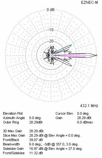
Fig. 8: Radiation patterns in H and V planes for sixteen antennas (V = 144+144+144 cm)
SIXTEEN ANTENNAS QY71310XL6D7 IN STACK (H=144+144+144 cm, V=162+162+162 cm)
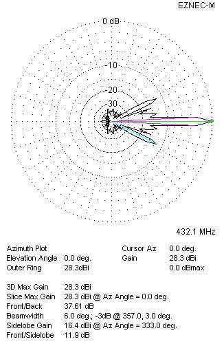
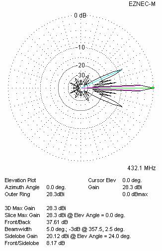
Fig. 9: Radiation patterns in H and V planes for sixteen antennas (V = 162+162+162 cm)
|
G (dBi) |
Hor (◦) |
Ver (◦) |
Temp (K) |
Tlos (K) |
G/T (dB) |
|
28.22 |
6.0 |
5.0 |
28.6 |
3.2 |
+13.66 |
Table 5: Performances of the sixteen antennas in a G/T optimized stack, corrected by the KF2YN correction formula
XPOL VERSION
If you need the antenna with both horizontal and vertical polarization, you can make it rather easily. All you need is another set of yagi-like elements, placing them vertically 20 milimetres behind the corresponding horizontal elements. The horizontal characteristics remains unchanged, but in order to get a proper 200 ohm impedance for the vertical section, the vertical set should be of the following length:
|
Ref |
De1 |
De2 |
D1 |
D2 |
D3 |
D4 |
|
331 |
330 |
330 |
294 |
301.5 |
288.5 |
278 |
Table 6 - Dimensions of the vertical elements
Then the radiation patterns for the vertical antenna section will look like Fig. 10.
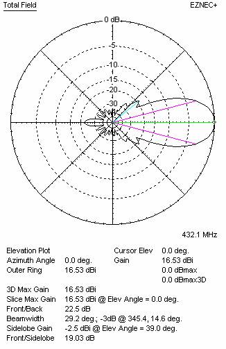
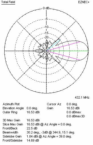
Fig. 10: Radiation patterns in H and V for the vertical part of the antenna
|
G (dBi) |
Hor (◦) |
Ver (◦) |
Temp (K) |
Tlos (K) |
G/T (dB) |
|
16.44 |
30.2 |
29.2 |
34.0 |
3.5 |
+1.13 |
Table 7 – Performances of the vertical part of the antenna, corrected by the KF2YN correction formula
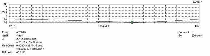
Fig. 11: Impedance diagram for the vertical part of the antenna for SWR better than 1.5

Fig. 12: Impedance diagram for the vertical part of the antenna from 432.1 to 435 MHz
Of course, the vertical part of the antenna should have clearance, too. In other words, no conducting materials must be present in front of its reflector. Supporting frames must be of insulating material, and the coaxial feedline must run behind the reflector. A possible solution can be seen in the figures 1 and 13 which shows 4x12 ele Hybrid antenna made by M0ABA.
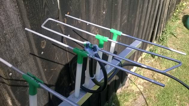
Fig. 13: Detail of 70cm Hybrid antenna made by M0ABA
PERFORMANCE CONSIDERATION
I wanted to know the real potential of the hybrid antennas. The VE7BQH G/T table is probably the best thing for this consideraton. I took a 2014 edition of this Table, with some modification, so that different models from different designers can be compared.
I do not claim that I am the best designer amongst all shown in the Table. Therefore some better results can be expected fron another modeller. Furtherly, the 200 OHM principle gives a bit lower results in the G/T value than the 50 Ohm system. Having all this in mind, I estimate that the performance potential of the hybrid antennas is at least 0.5 dB (in G/T) over other antenna types.
As far as I know, only a few hybrid antennas have been built and checked. They confirmed all qualities expected by EZNEC simulations, but I would be very happy to get results from antennas built by others.
|
TYPE OF |
SINGLE ANTENNA |
FOUR ANTENNAS IN H-STACK |
|||||||||||
|
L |
GAIN |
F/R |
Tlos |
Ta |
G/T |
Z |
VSWR |
E |
H |
Ga |
Ta |
G/T |
|
|
(ohms) |
Bandwidth |
||||||||||||
|
YU7EF EF7011B-5 |
2.87 |
15.07 |
25.4 |
4.7 |
|
|
49.0 |
1.56:1 |
1.20 |
1.11 |
21.00 |
36.1 |
5.43 |
|
Innov 11 LFA |
2.87 |
15.05 |
25.6 |
4.0 |
|
|
50.4 |
1.07:1 |
1.20 |
1.10 |
20.98 |
33.7 |
5.70 |
|
*Innov 11 LFA |
2.87 |
15.05 |
25.6 |
4.0 |
|
|
50.4 |
1.07:1 |
1.19 |
1.10 |
20.96 |
33.6 |
5.70 |
|
EAntenna 432LFA11 |
2.94 |
15.09 |
25.4 |
3.9 |
|
|
47.9 |
1.28:1 |
1.20 |
1.11 |
21.02 |
34.1 |
5.69 |
|
*KF2YN Polly 12 CR |
3.17 |
15.70 |
25.4 |
3.2 |
|
|
48.3 |
1.17:1 |
1.30 |
1.30 |
21.74 |
32.3 |
6.65 |
|
InnoV 12 LFA |
3.29 |
15.48 |
28.3 |
4.0 |
|
|
50.1 |
1.07:1 |
1.24 |
1.16 |
21.40 |
31.2 |
6.46 |
|
*InnoV 12 LFA |
3.29 |
15.48 |
28.3 |
4.0 |
|
|
50.1 |
1.07:1 |
1.23 |
1.15 |
21.37 |
31.0 |
6.46 |
|
YU7EF EF7012B-5 |
3.30 |
15.58 |
24.0 |
4.9 |
|
|
48.6 |
1.40:1 |
1.26 |
1.17 |
21.50 |
33.3 |
6.27 |
|
EAntenna 432LFA12 |
3.31 |
15.32 |
28.6 |
4.3 |
|
|
50.1 |
1.45:1 |
1.23 |
1.14 |
21.24 |
33.2 |
6.03 |
|
KF2YN Boxkite 13 |
3.37 |
17.38 |
28.0 |
9.3 |
|
|
50.9 |
1.09:1 |
1.63 |
1.50 |
23.29 |
39.4 |
7.35 |
|
Innov 13 LFA |
3.72 |
15.92 |
29.5 |
4.5 |
|
|
50.1 |
1.15:1 |
1.31 |
1.23 |
21.85 |
30.9 |
6.96 |
|
*innoV 13 LFA |
3.72 |
15.92 |
29.5 |
4.5 |
|
|
50.1 |
1.15:1 |
1.30 |
1.22 |
21.83 |
30.8 |
6.95 |
|
QY71310XL6D7 |
3.81 |
16.09 |
33.9 |
3.2 |
29.6 |
+1.38 |
200.2 |
1.06:1 |
1.44 |
1.62 |
22.18 |
28.7 |
7.60 |
|
YU7EF EF7013M-6 |
3.83 |
16.11 |
26.4 |
4.7 |
|
|
49.4 |
1.06:1 |
1.33 |
1.25 |
22.01 |
32.9 |
6.84 |
|
F9FT 19 |
4.02 |
15.96 |
21.5 |
6.1 |
|
|
55.7 |
1.14:1 |
1.33 |
1.26 |
21.88 |
39.1 |
5.96 |
|
DG7YBN Tonna 19 mod |
4.02 |
16.17 |
22.4 |
6.1 |
|
|
44.7 |
1.15:1 |
1.35 |
1.27 |
22.07 |
33.8 |
6.82 |
|
InnoV 14 LFA |
4.03 |
16.46 |
30.8 |
4.5 |
|
|
52.6 |
1.14:1 |
1.38 |
1.32 |
22.31 |
30.0 |
7.42 |
|
*InnoV 14 LFA |
4.03 |
16.46 |
30.6 |
4.5 |
|
|
52.6 |
1.14:1 |
1.36 |
1.29 |
22.26 |
30.0 |
7.40 |
|
+DG7YBN 14 |
4.06 |
16.38 |
26.9 |
3.5 |
|
|
49.4 |
1.51:1 |
1.38 |
1.31 |
22.30 |
30.7 |
7.42 |
|
YU7EF EF7014M-6 |
4.24 |
16.50 |
23.8 |
4.5 |
|
|
49.5 |
1.11:1 |
1.39 |
1.32 |
22.39 |
33.3 |
7.17 |
|
RA3AQ AQ70-14f |
4.30 |
16.63 |
26.1 |
6.9 |
|
|
52.8 |
1.09:1 |
1.41 |
1.34 |
22.54 |
33.6 |
7.28 |
|
KF2YN Boxkite 16 |
4.37 |
18.02 |
27.4 |
10.2 |
|
|
49.1 |
1.06:1 |
1.74 |
1.61 |
23.85 |
41.2 |
7.71 |
|
*KF2YN Polly 15 CR |
4.44 |
16.76 |
26.7 |
3.5 |
|
|
47.4 |
1.21:1 |
1.40 |
1.40 |
22.66 |
30.2 |
7.86 |
|
I0JXX 16JXX70 |
4.46 |
16.53 |
23.4 |
4.9 |
|
|
201.8 |
1.05:1 |
1.41 |
1.33 |
22.44 |
33.6 |
7.18 |
|
EAntenna 432LFA15 |
4.58 |
15.66 |
29.2 |
4.0 |
|
|
48.4 |
1.25:1 |
1.22 |
1.14 |
21.36 |
28.5 |
6.82 |
|
InnoV 15 LFA |
4.59 |
16.68 |
31.1 |
4.8 |
|
|
51.1 |
1.08:1 |
1.42 |
1.34 |
22.57 |
30.0 |
7.81 |
Table 8 – Modified VE7BQH table. The antenna QY71310XL6D7 is inserted where it belongs by its boomlength of 3.81λ.
Reference
(1) Slobodan Bukvic, YU7XL, Another Hybrid Antenna for 144 MHz, DUBUS 3/2014, pp76