|
ANTENNA QY236001XL3D55 |
|
|
|
DESCRIPTION |
||||
|
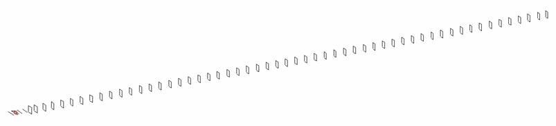
Radiator |
Number of yagi elements |
Number of oblong elements |
Total number of elements |
Boomlength (mm) |
|
LFA |
5 |
55 |
60 |
5515 |
|
DIMENSIONS |
||||||||||||||||
|
|
Ref |
De1 |
De2 |
D1 |
D2 |
D3 |
DQ1 |
DQ2 |
DQ3 |
DQ4 |
DQ5 |
DQ6 |
DQ7 |
DQ8 |
DQ9 |
DQ10 |
|
Position |
0 |
35 |
45 |
57 |
88 |
146 |
195 |
254 |
341 |
428 |
525 |
623 |
724 |
825 |
927 |
1026 |
|
Length |
112.0 |
116.0 |
980 |
103.4 |
103.2 |
99.0 |
58.8 |
57.2 |
55.0 |
54.2 |
52.4 |
52.2 |
51.4 |
50.8 |
50.2 |
49.6 |
|
|
DQ11 |
DQ12 |
DQ13 |
DQ14 |
DQ15 |
DQ16 |
DQ17 |
DQ18 |
DQ19 |
DQ20 |
DQ21 |
DQ22 |
DQ23 |
DQ24 |
|
Position |
1130 |
1231 |
1333 |
1433 |
1535 |
1635 |
1735 |
1836 |
1935 |
2035 |
2133 |
2234 |
2334 |
2435 |
|
Length |
48.4 |
47.8 |
47.4 |
47.0 |
46.8 |
46.6 |
46.4 |
46.2 |
46.2 |
46.2 |
46.2 |
46.2 |
46.0 |
46.0 |
|
|
DQ25 |
DQ26 |
DQ27 |
DQ28 |
DQ29 |
DQ30 |
DQ31 |
DQ32 |
DQ33 |
DQ34 |
DQ35 |
DQ36 |
DQ37 |
DQ38 |
|
Position |
2538 |
2638 |
2737 |
2833 |
2932 |
3032 |
3134 |
3234 |
3334 |
3434 |
3537 |
3638 |
3737 |
3836 |
|
Length |
46.0 |
46.0 |
46.0 |
46.0 |
46.0 |
46.0 |
46.0 |
46.0 |
46.0 |
46.0 |
46.0 |
46.0 |
46.0 |
46.0 |
|
|
DQ39 |
SQ40 |
SQ41 |
DQ42 |
DQ43 |
DQ44 |
DQ45 |
DQ46 |
DQ47 |
DQ48 |
DQ49 |
DQ50 |
DQ51 |
DQ52 |
|
Position |
3935 |
4034 |
4135 |
4234 |
4335 |
4434 |
4536 |
4635 |
4734 |
4832 |
4935 |
5036 |
5135 |
5234 |
|
Length |
46.0 |
46.0 |
46.0 |
46.0 |
46.0 |
46.0 |
46.0 |
46.0 |
46.0 |
45.0 |
45.0 |
45.0 |
45.0 |
45.0 |
|
|
DQ53 |
DQ54 |
DQ55 |
|
|
|
|
|
|
|
|
|
|
|
|
Position |
5331 |
5432 |
5515 |
|
|
|
|
|
|
|
|
|
|
|
|
Length |
45.0 |
45.0 |
45.0 |
|
|
|
|
|
|
|
|
|
|
|
|
REMARKS |
All elements made of CuAg wires Ǿ1.5 mm The height of rectangles is 60 mm All dimensions given in milimetres |
|
PERFORMANCES (No loss condition) |
|||||||
|
G (dBi) |
F/B (dB) |
F/Sh (dBi) |
F/Sv (dBi) |
Hor (◦) |
Ver (◦) |
Temp (◦K) |
G/T (dB) |
|
23.21 |
29.78 |
13.65 |
13.85 |
13.2 |
13.2 |
212.0 |
-0.03 |
|
PERFORMANCES (Loss included for silver) |
|||||||||
|
Aluminum |
G (dBi) |
TA (K) |
Tloss (K) |
G/T (dB) |
Bandwidth for SWR=1.5 (MHz) |
ΔF (MHz) |
|
||
|
After NEC/EZNEC |
23.21 |
14.2 |
|
+12.80 |
1275.000 – 1312.500 |
37.500 |
|||
|
After KF2YN correction |
23.04 |
21.6 |
7.1 |
+9.70 |
|||||
|
Remark |
|||||||||
|
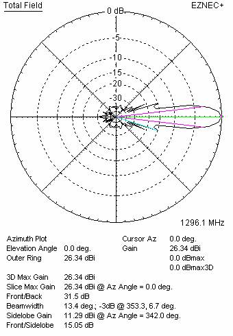
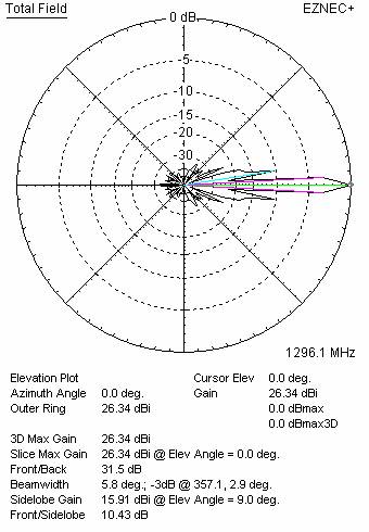
DIAGRAMS (no loss included) |
|
|
|
|
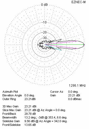
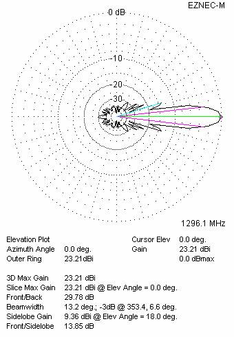
Horizontal and vertical pattern in free space, no loss condition
|
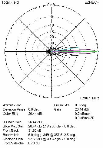
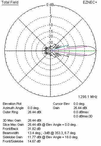
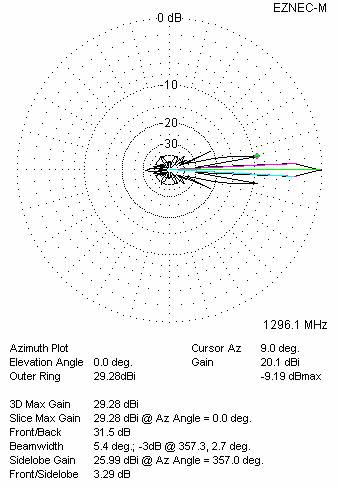
DIAGRAMS (loss included for silver) |
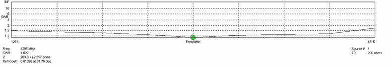
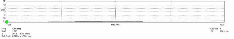
SWR diagram for the range from 1275.000 – 1315.000 MHz and 1296 – 1300 MHz
|
|
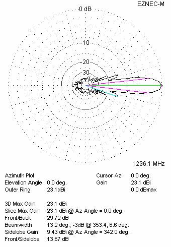

Horizontal and vertical pattern in free space, loss included for silver
|
STACKING (ALL DATA GIVEN IN ACCORDANCE WITH KF2YN CORRECTION, LOSS INCLUDED FOR SILVER) |
|
RECOMMENDED STACKING DISTANCES |
|||
|
|
Two antennas vertically (mm) |
Two antennas horizontally (mm) |
Four antennas i H-stack (mm) |
|
Vertical distance |
1040 |
|
1040 |
|
Horizontal distance |
|
1080 |
1080 |
|
TWO ANTENNAS STACKED VERTICALLY |
|||||
|
DISTANCE |
G |
TA |
G/T |
Tloss |
|
|
1040 |
26.00 |
20.6 |
+12.86 |
7.1 |
|