ANTENNA QY20610XL4D1
ANTENNA QY20610XL4D1
PERFORMANCES:
|
No of ele |
L (mm) |
G (dBi) |
F/B (dB) |
F/Sh (dBi) |
F/Sv (dBi) |
Hor (◦) |
Ver (◦) |
Temp (◦K) |
G/T (dB) |
Tlos (K) |
|
6 |
1865 |
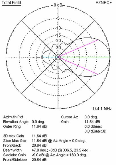
11.55 |
20.64 |
20.74 |
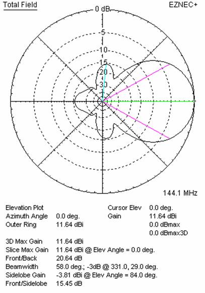
15.45 |
47.0 |
58.0 |
296.7 |
-13.17 |
2.6 |
WORKING CONDITION:
|
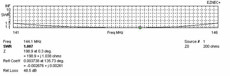
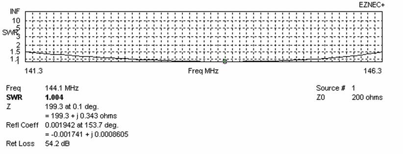
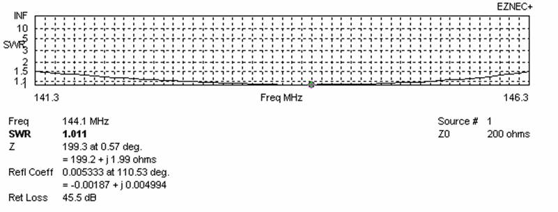
Frequency for SWR=1.5 (MHz) |
Z (Ώ) at 144.100 MHz |
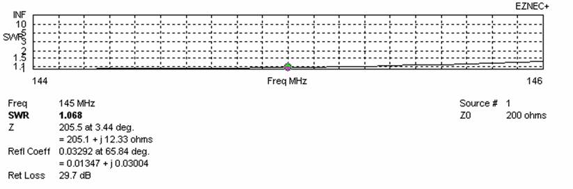
SWR at 145.000 MHz |
||
|
Lowest |
Highest |
Bandwidth |
||
|
141.300 |
146.300 |
5.000 |
199.2 |
1.07:1 |
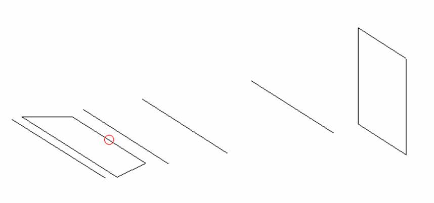
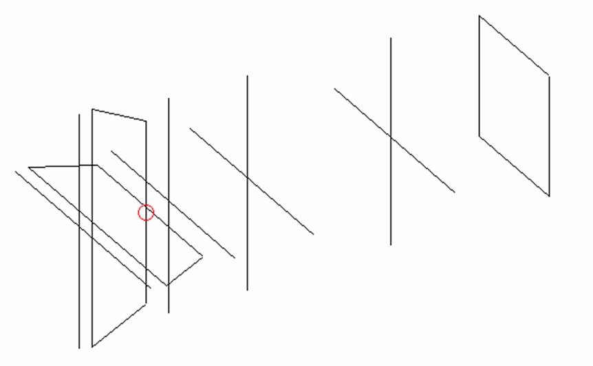
DIMENSIONS:
|
|
Ref |
De1 |
De2 |
D1 |
D2 |
D3 |
DQ1 |
All elements made of Al tubes Ǿ10 mm The height of the rectangle is 522 mm All dimensions given in milimetres |
|
Pos |
0 |
60 |
290 |
389 |
729 |
1349 |
1865 |
|
|
Length |
1016 |
1032 |
796 |
930 |
930 |
902 |
522 |
No boom correction included.
COMPARISON
|
TYPE OF ANTENNA |
SINGLE ANTENA |
FOUR ANTENNAS IN H-STACK |
||||||||
|
L (λ) |
GAIN (dBd) |
Z (ohms) |
VSWR Bandwidth |
E (m) |
H (m) |
Ga (dBd) |
Tlos (K) |
Ta (K) |
G/T (dB) |
|
|
QY20610XL4D1 |
0.90 |
9.40 |
199.2 |
1.07:1 |
3.04 |
1.98 |
15.38 |
2.4 |
242.5 |
-6.32 |
|
G4CQM 6 |
1.00 |
9.46 |
56.7 |
1.83:1 |
2.60 |
2.17 |
15.44 |
7.9 |
249.7 |
-6.38 |
|
KF2YN boxkite6 |
1.04 |
12.47 |
49.9 |
1.20:1 |
3.90 |
3.00 |
18.25 |
4.6 |
263.1 |
-3.80 |
|
Vine 6 FD |
1.10 |
9.69 |
48.3 |
1.18:1 |
2.64 |
2.21 |
15.67 |
8.2 |
238.4 |
-5.95 |
|
G0KSC 6LFA |
1.13 |
9.69 |
49.3 |
1.04:1 |
2.60 |
2.19 |
15.64 |
4.0 |
236.9 |
-5.96 |
|
DD0VF 6 |
1.16 |
9.73 |
27.2 |
1.07:1 |
2.63 |
2.22 |
15.71 |
5.5 |
240.1 |
-5.94 |
|
M2 2M7 |
1.28 |
9.94 |
204.9 |
1.14:1 |
2.65 |
2.26 |
15.76 |
3.7 |
245.0 |
-5.98 |
|
Z(ohms) - measured on 144.100 MHz Bandwidth – VSWR measured on 145.000 MHz Data taken from VE7BQH G/T table |
||||||||||
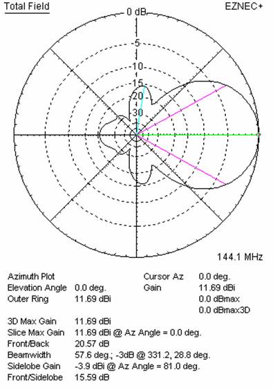
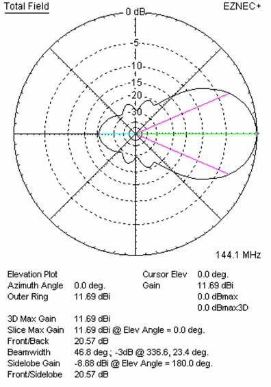
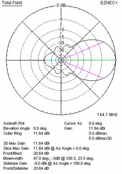
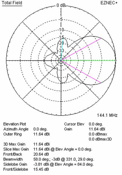
DIAGRAMS (no loss included)
SWR DIAGRAMS (loss included for Al)
STACKING
|
Horizontal distance (cm) |
G (dBi) |
TA (K) |
G/T (dB) |
Vertical distance (cm) |
G (dBi) |
TA (K) |
G/T (dB) |
|
100 |
|
|
|
100 |
13.23 |
249.3 |
-10.74 |
|
110 |
12.65 |
310.1 |
-12.27 |
110 |
13.41 |
243.1 |
-10.45 |
|
120 |
12.98 |
297.3 |
-11.75 |
120 |
13.57 |
239.9 |
-10.23 |
|
130 |
13.20 |
291.2 |
-11.44 |
130 |
13.69 |
240.3 |
-10.11 |
|
140 |
13.39 |
288.1 |
-11.21 |
140 |
13.78 |
243.3 |
-10.08 |
|
150 |
13.55 |
286.9 |
-11.03 |
150 |
13.86 |
245.6 |
-10.04 |
|
160 |
13.69 |
287.1 |
-10.89 |
160 |
13.97 |
244.6 |
-9.91 |
|
170 |
13.81 |
288.3 |
-10.79 |
170 |
14.11 |
241.8 |
-9.72 |
|
180 |
13.93 |
290.0 |
-10.69 |
180 |
14.25 |
239.7 |
-9.55 |
|
190 |
14.04 |
292.2 |
-10.62 |
190 |
14.38 |
240.1 |
-9.42 |
|
200 |
14.14 |
294.4 |
-10.55 |
200 |
14.48 |
243.3 |
-9.38 |
|
210 |
14.23 |
296.4 |
-10.49 |
210 |
14.56 |
249.3 |
-9.40 |
|
220 |
14.32 |
298.3 |
-10.43 |
220 |
14.62 |
257.3 |
-9.48 |
|
230 |
14.39 |
299.8 |
-10.38 |
230 |
14.66 |
266.5 |
-9.60 |
|
240 |
14.46 |
300.9 |
-10.33 |
240 |
14.69 |
276.4 |
-9.72 |
|
250 |
14.52 |
301.6 |
-10.28 |
250 |
14.70 |
286.2 |
-9.87 |
|
260 |
14.57 |
301.9 |
-10.23 |
260 |
14.71 |
295.5 |
-10.00 |
|
270 |
14.61 |
301.9 |
-10.19 |
270 |
|
|
|
|
280 |
14.64 |
301.6 |
-10.16 |
280 |
|
|
|
|
290 |
14.67 |
301.1 |
-10.12 |
290 |
|
|
|
|
300 |
14.69 |
300.4 |
-10.09 |
300 |
|
|
|
|
310 |
14.70 |
299.7 |
-10.07 |
310 |
|
|
|
|
320 |
14.71 |
298.9 |
-10.05 |
320 |
|
|
|
|
330 |
14.72 |
298.1 |
-10.02 |
330 |
|
|
|
|
340 |
14.72 |
297.4 |
-10.01 |
340 |
|
|
|
|
350 |
14.71 |
296.8 |
-10.02 |
350 |
|
|
|
|
360 |
14.71 |
296.3 |
-10.01 |
360 |
|
|
|
*The Table is presented without KF2YN convergence correction applied and serves only to show which distance can be used with good result,
and which distances should be avoided. In H-stack it can be slightly changed.
BEST DISTANCES FOR 4 ANTENNAS IN H-STACK
|
Horizontal distance (cm) |
Vertical distance (cm) |
G (dBi) |
TA (K) |
G/T (dB) |
Remark |
|
261 |
215 |
17.55 |
257.4 |
-6.55 |
Per DL6WU formula |
|
304 |
198 |
17.52 |
242.5 |
-6.32 |
For max G/T |
|
314 |
178 |
17.31 |
236.8 |
-6.43 |
For lowest temperature |
XPOL VERSION
Horizontal components: Same as above
Vertical components: Same as above, except:
PERFORMANCES:
|
Polarization |
G (dBi) |
F/B (dB) |
F/Sh (dBi) |
F/Sv (dBi) |
Hor (◦) |
Ver (◦) |
Temp (◦K) |
G/T (dB) |
Tlos (K) |
|
Horizontal |
11.55 |
20.64 |
20.64 |
15.45 |
47.0 |
58.0 |
296.7 |
-13.17 |
2.6 |
|
Vertical |
11.60 |
20.57 |
15.59 |
20.84 |
57.6 |
46.8 |
269.7 |
-12.71 |
2.9 |
Horizontal polarisation patterns
Vertical polarisation patterns