Vintage Radio Page

 Described on my blog My grandfather's Blaupunkt radio
Article in Norwegian in Hallo
Hallo September 2001: "My
grandfather's Blaupunkt radio".
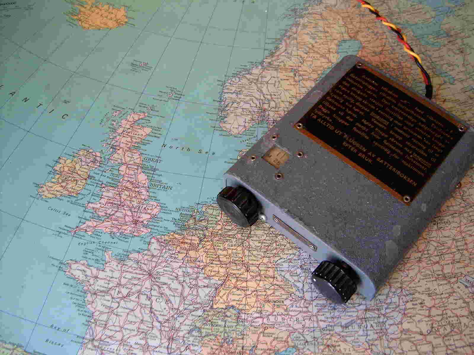
This is a miniature radio designed by Willy
Simonsen
in London during the second world war and dropped in
large numbers behind enemy lines all over Europe. It is a regenerative
radio with three identical IT4 (DF91) miniature valves and it runs from
two batteries: 4.5 Volt and 30 Volts. It covers the major shortwave
broadcast bands (25-50 m), and one of its usages was reception of coded
messages over the BBC broadcasts. Mine is serial no. 11800 and it works
fine, but unfortunately it has unoriginal knobs.
This radio was brought to Norway from the US by my father in the late
forties. Here's his QSL-card
from 1949 for a QSO using this radio. He replaced the power transformer
to convert it to 230 VAC operation and added an EM34 magic eye. Because
of its coverage up to 44 MHz, it was used to receive the Sputnik
downlink in 1957.
In the late sixties I got the
schematics diagram from Hallicrafters and I added a product detector
for SSB-demodulation, audio derived AGC for SSB (replacing the 6J5 with
a 6SN7), an 85A2 voltage regulator for the oscillator, and an S-meter
output. When I fired it up again recently, the sensitivity was very
poor, so I started to tune the IF-transformers. I discovered that one
of them was impossible to tune to maximum, so I opened the can and
found a loose connection to the tuning capacitor. After that was fixed
it worked like never before. After some months of frequent use I had to
replace a couple of paper type 0.02 microF capacitors
that short-circuited, and
several other 0.05 microF leaky capacitors. A final modification was to
move the headphone output to the output of the audio transformer rather
than the grid of the output stage, as this fits the impedance and
sensitivity of modern headphones much better.
- Tubes: 6SG7 (RF), 6SA7
(mixer), 2 x 6SK7 (IF), 6H6 (detector and noise limiter), 6J5 (BFO),
6SQ7 (AF), 6F6-G (AF output), and 80 (the schematic says 5Y3GT for the
rectifier).
- Circuit diagram of S-meter:
All components with numbers above 100 have been added. The circuit
measures the cathode current of the last IF tube, V4, by comparison
with an 8 Volt reference voltage from the zener diode Z101. R101 and
Z101 replace R24 (680 ohms) in the cathode circuit of the final AF
stage, V6. D101 is any diode with a low forward voltage drop
(preferably Ge). The meter I use is a 100 micro Amps miniature S-meter,
but a less sensitive meter can also be used. Adjust R102 for zero
reading for noise only reception or when the AVC control is off, then
adjust the sensitivity control R104 for a full scale reading
corresponding to a real strong signal.
This circuit is safer than the one described elsewhere
as it does not require you to connect to the high voltage part of the
circuitry.
Links:
I bought this radio from a friend in the mid-sixties. It is an early
miniature radio with germanium transistors. It has FM, MW and LW bands,
and plays beautifully.
Last update 30 October 2005.
© LA3ZA, Sverre
Holm