6cms Antennas
Almost all operation on 6cms is done with dish antennas. Of course it is possible to use Yagis if they are scaled correctly, but the dish offers much more gain and is probably easier and cheaper to build because dishes are available for the satellite television market. Another big advantage is that dishes are not intrinsically frequency sensitive, it is the dish feed that is specific to the frequency in use. Therefore this page will concentrate exclusively on the different dish feed designs that can be used on 6cms. It will be assumed that the dish will have an accurate profile at 5.7GHz, if the dish is designed for satellite television (11 to 12GHz in Europe) then it should be more than accurate enough. My own dish was bought from a local satellite television dealer.
Until relatively recently there were no companies making antennas or feeds for 6cms (or 3cms for that matter), but now this has changed and two companies/people have arrived on the scene and they are referenced further down in the page. If you wish to build your own, an extremely good source of information about dish feeds and microwave antennas in general can be found in the W1GHZ antenna manual. While it is a very good source of theoretical information, the book is a little short on practical designs to build.
Single Band Feeds
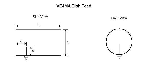
The most popular single band dish feed design is from VE4MA which is optimised for an f/D ratio of around 0.4. Put simply this feed consists of a length of tube, closed at one end, with a connector with a probe fitted in order to it to introduce the RF into the feed. Of course the lengths and diameters of the various parts is important. I don't have a copy of the original VE4MA article with his recommended sizes, but I can give some dimensions used by other people.
Using the table below, dimension A is the diameter of the tube while B is the length of the tube, of these dimension A is the most important (see W1GHZ) whereas dimension B is anything you like over a certain length.
Dimension C is the distance of the probe from the plate covering the closed end of the tube, and dimension D is the length of the probe. Unfortunately I have no information about the diameter of the probes used. Try 1mm.
All dimensions are in mm.
| Call Sign | A | B | C | D |
| G3PHO | 38 | 69.5 | 22 | 11.5 |
| OE8MI | 33 | 100 | 15 | 11.5 |
OE8MIs version of the feed can be seen in the following photographs.
![]() Rear view of the 3cms and 6cms feeds.
Rear view of the 3cms and 6cms feeds.
![]() Side view of the 3cms and 6cms feeds.
Side view of the 3cms and 6cms feeds.
WB5LUA Dual-Band Feed
The only dual-band feed for both 3cms and 6cms that I know of is the WB5LUA design. This is the design that I used. A full design using pipe fittings is given in the W1GHZ handbook mentioned above, it has been reported that HA1YA has a dual-band feed similar to the popular 3cms/12mm dual-band feed. In that design, the higher band uses a standard SMA/N to waveguide transition and the lower band is built similar to the VE4MA feed design. In both designs, the feed for the higher band does not affect the lower band as the waveguide for that band is too small for the wavelength of the higher band and therefore does not appears as a hole.
One problem with dual-band feeds is that the isolation when transmitting on the higher band and receiving on the lower one is rather low. In order not to damage the receive front end of the lower band some form of protection is needed. A technique suggested by DL6NCI is to put the lower band onto transmit at the same time as the higher band, in that way the power (measured in the low milliwatts typically) is fed into the lower bands PA which can easily handle such power being returned, especially off frequency.
![]() The original WB5LUA design.
The original WB5LUA design.
For my system I used the WB5LUA design but had it made at a precision workshop from a single piece of Aluminium. The length of the 6cms portion of the feed was set to be mid way between the two values given by WB5LUA.
![]() The engineering drawings as a PDF file.
The engineering drawings as a PDF file.
When adjusting the feed, we (myself and Dominik HB9CZF) first adjusted the 6cms feed by trimming the length of the probe, with a dummy load connected to the 3cms feed. Once that was done, the dummy load was connected to the 6cms feed and the length of the 3cms probe was made to the same dimensions as given by WB5LUA and then adjusted the screw for the best match.
![]() Side view of the finished feed.
Side view of the finished feed.
![]() End view of the finished feed.
End view of the finished feed.
After adjustments, the return loss on both bands was in excess of 20dB.
Thank you to Dominik HB9CZF for helping me to adjust my dish feed, and for taking the photographs.
The WB5LUA feed design is now being sold commercially by Down East Microwaves.
Others
An alternative were the feeds made and sold by Hans DD7MH. These were based on the DJ9HO loop antennas and were specifically designed for use with offset fed dishes which have an f/D ratio of approximately 0.7, which is unsuitable for the WB5LUA design. I have used one of his dual-band feeds for 6/3cms and have been very happy with it, however some tests results made at Martlesham 2003 appeared to show a very low gain compared to a similar sized dish fed with a more conventional horn arrangement. I will be looking at maybe changing my feed as some future date.
Last modified on 30.11.2003