
ANTENNA X21608XL2Q
PERFORMANCES:
|
No of ele |
L (mm) |
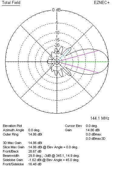
G (dBi) |
F/B (dB) |
F/Sh (dBi) |
F/Sv (dBi) |
Hor (◦) |
Ver (◦) |
Temp (◦K) |
G/T (dB) |
Tlos (K) |
|
16 |
3605 |
14.94 |
28.67 |
25.37 |
16.48 |
38.7 |
29.8 |
225.6 |
-8.69 |
4.5 |
WORKING CONDITION:
|
Frequency for SWR=1.5 (MHz) |
Z (Ώ) at 144.100 MHz |
SWR at 145.000 MHz |
||
|
Lowest |
Highest |
Bandwidth |
||
|
141.000 |
146.600 |
5.600 |
199.1 |
1.07:1 |
DIMENSIONS:
|
|
Ref |
De |
D1 |
D2 |
D3 |
D4 |
D5 |
D6 |
D7 |
Dimensions given in milimetres Diameter of elements 8 milimetres No boom correction included.
|
|
Pos |
0 |
238 |
398 |
768 |
1204 |
1684 |
2336 |
3034 |
3605 |
|
|
Length |
1012 |
792 |
931 |
927 |
933 |
919 |
907 |
903 |
891 |
|
|
Height |
0 |
±230 |
±230 |
±385 |
±520 |
±615 |
±695 |
±705 |
±695 |
CONSTRUCTION OF RADIATOR
H = 792
V = 230
Ø= 8 mm

COMPARISON (inserted in a part of VE7BQH table, where it belongs according to its boom length)
|
TYPE OF ANTENNA |
SINGLE ANTENA |
FOUR ANTENNAS IN H-STACK |
||||||||
|
L (λ) |
GAIN (dBd) |
Z (ohms) |
VSWR Bandwidth |
E (m) |
H (m) |
Ga (dBd) |
Tlos (K) |
Ta (K) |
G/T (dB) |
|
|
X21608XL2Q |
1.73 |
12.73 |
199.1 |
1.07:1 |
3.80 |
4.10 |
21.00 |
4.5 |
223.5 |
-2.49 |
|
G0KSC 8LFA |
1.79 |
11.06 |
50.0 |
1.24:1 |
3.15 |
2.40 |
16.95 |
3.6 |
222.2 |
-4.37 |
|
W1JR 8 MOD |
1.80 |
11.14 |
50.0 |
1.14:1 |
3.07 |
2.75 |
16.99 |
5.3 |
256.7 |
-4.95 |
|
DJ9BV 1.8 |
1.80 |
11.34 |
77.5 |
1.34:1 |
3.16 |
2.80 |
17.28 |
5.5 |
261.2 |
-4.74 |
|
K1FO 10 |
1.84 |
11.34 |
29.4 |
1.44:1 |
3.10 |
2.78 |
17.27 |
4.3 |
257.7 |
-4.69 |
|
Vine 8 FD |
1.85 |
11.18 |
51.4 |
1.12:1 |
3.00 |
2.63 |
17.06 |
8.5 |
232.3 |
-4.45 |
|
YU7EF 8 |
1.87 |
11.31 |
48.5 |
1.21:1 |
3.04 |
2.71 |
17.23 |
3.8 |
242.1 |
-4.46 |
|
BQH8B |
1.88 |
11.60 |
50.0 |
1.29:1 |
3.28 |
2.97 |
17.62 |
7.2 |
259.3 |
-4.37 |
|
UR5EAZ 9 |
1.89 |
11.32 |
49.2 |
1.01:1 |
3.07 |
2.75 |
17.26 |
3.6 |
249.7 |
-4.56 |
|
G4CQM 8 |
1.91 |
11.52 |
49.5 |
1.11:1 |
3.15 |
2.83 |
17.45 |
5.1 |
248.5 |
-4.35 |
|
KF2YN Boxkite9 |
1.92 |
13.98 |
49.2 |
1.28:2 |
4.45 |
3.70 |
19.95 |
5.6 |
228.6 |
-1.48 |
|
CT1FFU 8 |
1.94 |
11.28 |
27.1 |
1.05:1 |
2.96 |
2.62 |
17.10 |
2.9 |
232.3 |
-4.41 |
|
G0KSC 8OWL |
1.95 |
11.63 |
48.9 |
1.26:1 |
3.13 |
2.82 |
17.55 |
4.6 |
235.7 |
-4.02 |
|
Z(ohms) - measured on 144.100 MHz Bandwidth – VSWR measured on 145.000 MHz |
||||||||||
DIAGRAMS (no loss included)

SWR DIAGRAMS (loss included for Al)


STACKING
|
Horizontal distance (cm) |
G (dBi) |
TA (K) |
G/T (dB) |
Vertical distance (cm) |
G (dBi) |
TA (K) |
G/T (dB) |
|
100 |
|
|
|
100 |
|
|
|
|
110 |
|
|
|
110 |
|
|
|
|
120 |
|
|
|
120 |
|
|
|
|
130 |
|
|
|
130 |
|
|
|
|
140 |
16.18 |
223.4 |
-7.35 |
140 |
|
|
|
|
150 |
16.36 |
222.4 |
-7.16 |
150 |
|
|
|
|
160 |
16.52 |
222.3 |
-6.99 |
160 |
|
|
|
|
170 |
16.66 |
222.8 |
-6.86 |
170 |
|
|
|
|
180 |
|
|
|
180 |
|
|
|
|
190 |
|
|
|
190 |
|
|
|
|
200 |
17.00 |
225.8 |
-6.58 |
200 |
15.85 |
268.8 |
-8.46 |
|
210 |
|
|
|
210 |
|
|
|
|
220 |
|
|
|
220 |
|
|
|
|
230 |
|
|
|
230 |
|
|
|
|
240 |
|
|
|
240 |
|
|
|
|
250 |
17.40 |
228.9 |
-6.24 |
250 |
16.90 |
229.4 |
-6.75 |
|
260 |
|
|
|
260 |
17.02 |
226.2 |
-6.57 |
|
270 |
|
|
|
270 |
17.12 |
223.9 |
-6.42 |
|
280 |
|
|
|
280 |
17.21 |
223.2 |
-6.32 |
|
290 |
|
|
|
290 |
17.27 |
224.6 |
-6.29 |
|
300 |
17.67 |
226.5 |
-5.92 |
300 |
|
|
|
|
310 |
|
|
|
310 |
|
|
|
|
320 |
17.74 |
224.8 |
-5.82 |
320 |
|
|
|
|
330 |
17.77 |
224.0 |
-5.78 |
330 |
|
|
|
|
340 |
17.79 |
223.4 |
-5.74 |
340 |
17.54 |
230.1 |
-6.12 |
|
350 |
17.81 |
222.9 |
-5.71 |
350 |
17.60 |
228.3 |
-6.02 |
|
360 |
17.83 |
222.6 |
-5.69 |
360 |
17.66 |
226.6 |
-5.93 |
|
370 |
17.84 |
222.5 |
-5.68 |
370 |
17.71 |
225.4 |
-5.86 |
|
380 |
17.85 |
222.6 |
-5.67 |
380 |
17.76 |
224.7 |
-5.80 |
|
390 |
17.85 |
223.0 |
-5.68 |
390 |
17.79 |
224.7 |
-5.77 |
|
400 |
17.85 |
223.4 |
-5.69 |
400 |
17.82 |
225.2 |
-5.75 |
|
|
|
|
|
410 |
17.84 |
226.1 |
-5.74 |
|
|
|
|
|
420 |
17.85 |
227.0 |
-5.75 |
*The Table is presented without KF2YN convergence correction applied and serves only to show which distance can be used with good result, and which distances should be avoided. In H-stack it can be slightly changed.
*Yellow coloured – good distances
BEST DISTANCES FOR STACK
Four antennas in H-stack
|
Horizontal distance (mm) |
Vertical distance (mm) |
G (dBi) |
TA (K) |
G/T (dB) |
Tlos (K) |
Remark |
|
3147 |
4019 |
20.82 |
227.9 |
-2.75 |
4.5 |
Per DL6WU formula |
|
3800 |
4100 |
21.00 |
223.5 |
-2.49 |
4.5 |
For max G/T |
|
1620 |
3900 |
19.57 |
223.3 |
-3.92 |
4.5 |
For lowest temperature |

Four antennas in H-stack, H=3.80+3.80+3.80 V=4.10+4.10+4.10 metres


Eight antennas in stack (four in horizontal and two in vertical plane)
|
Horizontal distance (mm) |
Vertical distance (mm) |
G (dBi) |
TA (K) |
G/T (dB) |
Tlos (K) |
|
3800 |
4100 |
23.99 |
223.2 |
+0.40 |
4.5 |


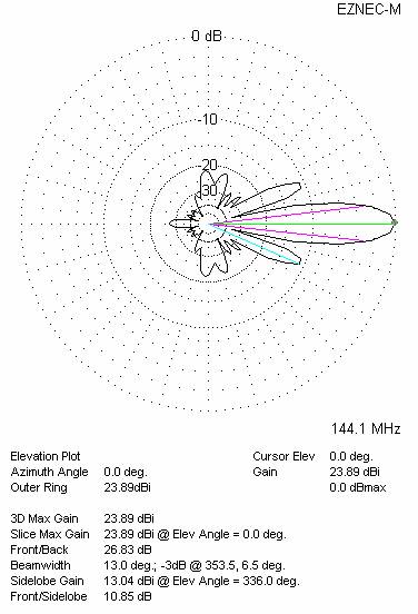
Sixteen antennas (four in horizontal and four antennas in vertical plane)
|
Horizontal distance (mm) |
Vertical distance (mm) |
G (dBi) |
TA (K) |
G/T (dB) |
Tlos (K) |
|
3800 |
4100 |
26.96 |
232.0 |
+3.31 |
4.5 |
SIXTEEN ANTENNAS AT H=3.80+3.80+3.80 AND V=4.10+4.10+4.10 METRES - DIAGRAMS


