Updates:


ROVERBOX - display unit
a stand-alone GPS module monitor


please subscribe to the mailinglist for notifications -- http://groups.yahoo.com/group/roverbox/ 


BOX PIC
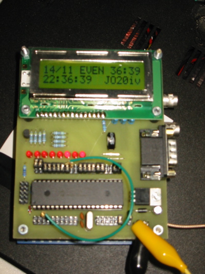
The Roverbox stack, LCD/PIC module on top, GPS OEM board and 10Mhz reference
below - the two 10 MHz BNC outputs and GPS antenna pigtail are visible at the right.


RB-lcd-metersrb-lcd-satsrb-lcd-sat
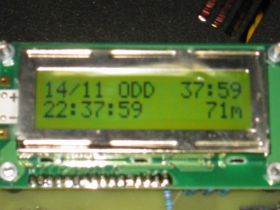
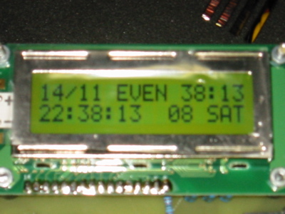
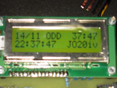
Alternating display mode.

0. Introduction.

The Roverbox display unit was originally a stand-alone device to provide useful (microwave) operating info based on a GPS module. OEM GPS modules provide lots of info for cheap, but having a complete terminal (like a PC) to monitor the output is not very handy in the field. It is now loosely coupled (show combo, hi-res 300K) with the N1JEZ/G3RUH/W1GHZ GPS based 10MHz  reference, but can be used without the reference as well. The Roverbox is basically PIC16f877a and an 2*16 LCD - that's all. I built the first prototype in 2004 after disussion with W3IY. The work on the 10MHz reference encouraged me to take it a bit further than originally intended.

Note that for those just wanting a lock indicator for the 10MHz reference a simpler PIC with 1 LED is available (see Mike N1JEZ MUD 2005 article).

If you don t fully grasp how everything fits together: look here.

1. Functionality.

The following information is provided on the LCD:
Some control funtions are also available as digital PIC outputs, such as lock/unlock status.

1. Hardware.

The Roverbox display unit uses the backlit board from DELTAWAVE (look on German Ebay or Google)- for 32EUR or 40USD one get's a complete board with PIC, LCD, true RS-232 conversion (MAX232) and In-Circuit Programming capability. That's hard to beat!  If you live outside Europe and have trouble ordering, I  have some (programmed) boards available.

Some DELTAWAVE specific info:

2. Software.

*** Versions below are written in CCS C. A really useful tool for serious PIC enthousiast and not expensive. A free version is available as well as a student version. For this particular application an interrupt service routine is used for the GPS data, and extensive use is made of the included libraries for floating point and math calculations. I am currently only providing the *.hex files, but Email if you need anything.  ***

V32-DW V32-4-DW V32-77-DW V32-4-77-DW.
V31-DW V31-4-DW V31-77-DW V31-4-77-DW. Fixes bug in locator calculation. 77 is for 16F877 other 877a. 4 is for 4 MHz Xtal.

V30-DW This is the general release of the new code. Includes Az/El and features a revised display set-up, with locator always on screen, and less space for Odd/Even.
V30-4DW Same for 4MHz Xtal.

LED codes


V30a2-DW This is a completely new ALPHA version of the software, now also showing sun azimuth and elevation as one of the alternating screens. The experimental code has been merged with the normal track. Better error handling, and some meaningful error messages. The PIC now runs at 98% ROM and 99% RAM, getting everything to fit was a big issue, so this will be the final word in terms of functionality. Except for sun Az/El the functionality is largely similar to V24-DW.

LED codes

Available info *** All versions below are written in JAL (this guy also has a great shop and programmers, not the usual $)$%#@%), and use no interrupts. It is "just" parsing of the serial strings coming from the GPS. I feel we are reaching some of the limits of this approach and I am starting to miss floats, especially for sun Az/El, so a rewrite/port to C may be needed soon. Also the current code is in need of a clean-up, but I like to do radio once in a while too. For all of the above I am currently only providing the *.hex files, but Email if you need anything.  ***

V24-DW Serial port routines rewritten so update is more fluent. Seconds dropped from LCD in lower left corner, since this was already in upper right when data is valid. For the experimental track LCD now shows: locator (during 5 seconds) - sats/height (5 seconds total) -  HDOP (1 second). LED codes unchanged.
V24-4DW Same for 4MHz Xtal.

V23-DW Some enhancements to the experimental track. HDOP is now now shown in the display as well as height and # of sats. If for some reason (GPS validity lost or HDOP becomes too big (>1.99)) the accuracy gets questionable a warning "?" is displayed in front of the locator field. The digital output however reflects validity in the GPRMC statement only. LED codes unchanged.

V22-DW Runs on stock DELTAWAVE hardware, bugfixes and features as V20. However experimental code can be enabled by connecting A1 to +5V at startup, disable by connecting to ground (either one required, but the board will flag EXPERIMENTAL when running the exp. code). The experimental code will provide you with locator, # sats and height, shown alternating on the LCD.
LED codes
V20-3.6MHz This version was the first for the DELTAWAVE board and the first to be publically distributed.

LED codes

3. Installation and troubleshooting.

Only 1 connection is needed from the GPS board  to the DELTAWAVE hardware. GPS 20 pin header pin 11 (serial out) must be connected to pin 26 of the PIC. Of course the GPS/PIC OEM boards need power and the correct NMEA initialization, but much info is available from N1JEZ and www.GPSKIT.nl.

V-3x Problems:

    The Display Unit now displays more meaningful errors (at least to me).
   

V-2x Problems:
  1. Upon power-up without GPS the display should give an initialization message and indicate standard/experimental mode, then "NO GPS".
  2. B0 lit and B1 does not blink - software error or GPS connection lost in a critical blocking read > please reset.
  3. B0 lit and B1 blinks irregularly, but no info on display - the GPS detects OK, and serial data is coming in, but "wrong Baud rate" error, bad GPS init (no NMEA format send by GPS) or Xtal out-of-spec. 
  4.  B0 lit and B3 remains lit - validity can not be achieved with current coverage, date may be wrong, out-of-lock > improve reception. The GPS data is only valid if minutes:seconds are displayed in the upper-right corner.

4. Considerations regarding the 10MHz reference.

Accuracy

We need to investigate what the impact is of bad GPS weather (e.g. constellation) on the 10MHz output in this simple, non-position hold approach. It is not easy to find exact information on this subject (please correct me), but values of a 100m PDOP (95%) typically result in 350ns (95%) timing error. This is typically the "normal" accuracy we used to get with SA enabled. That error reduces our 10MHz accuracy  to the order of 1E-6/7, or on 47 GHz to 5-50kHz. There goes our QSO! Currently without SA the situation has improved dramatically but accuracy claims must be regarded with caution. Typically position accuracy is now 10-15m both horizontal and vertically for the SPS, with H/V-DOP around 2-3. That brings us to around 1E-8, or 0.1 Hz on 10MHz. The above numbers are for the 95% confidence interval, so even smaller numbers will typically apply in practice. The MUD 2005 claimed value of  a bit less 1E-9 seems somewhat optimistic but can be achieved under good circumstances like with 1m DOPs.

Lock indication

It is a bit tricky to assess PLL lock based on the GPS info, of course. Currently I do this simply based on the validity indication in the $GPRMC sentence. However the fix quality indicator (SPS, Standard Position Service) or 3-D fix of the $GPGGA/GSA sentences may be better suited - I need to validate this in some more detail. The latter is a bit more conservative on our stock GPS boards.
An even better solution would be to do an interpretation of the HDOP or PDOP field that indicates the position quality and as such also the timing quality. This is already shown on the LCD in versions 23+. I am still not really happy with this lock indication, it seems to take up 1min for lock to occur after GPS validity or small enough HDOP is achieved.

Construction

The MAX233 of the PLL board can be left out since the DELTAWAVE PIC board already has this available. It is sufficient just to wire the RX and TX data pins of the PIC together so that the data flows both into the PIC processor as well as out of the MAX232 chip into the DTE.

For European builders of the 10MHz reference PLL board all components are available from RS-components.

Results and measurements (at ON4IY)


I did some quick measurements recently, and H/V-DOP and PDOP where consistently around 1/1/1-2 as reported by my TU-30 GPS module, which has good coverage (typically 8 sats available) -- so the above numbers and associated accuracy could well be realistic.

The output of my simple 10MHz can be seen in the following SpectrumLab pictures, this looks very promising as the +/-1E-9 is available:

10M init 10M drift
Convergence towards the HP Z3801A reference signal shown in the bottom half of the picture (left)
130th harmonic (1.3 GHz) with +/- 1.5Hz (3Hz max-min, hor. scale 1Hz) deviation (right)


I checked the output on 10MHz using the HP 5370B time interval counter accurate to around 1mHz - without added statistical processing at 1s gate time. I measured max-min to be around 25mHz, as expected. You can find this counter often on Ebay at low prices!

The output contains many harmonics as illustrated above. I recommend using a 10base-X filter like the 20f001n to clean up things a little. These filters can be found in discarded Ethernet hubs or similar and provide 20dB suppression at 20MHz. This often eliminates lock issues like on older measurement equipment.

5. Solar position calculations.

The low accuracy algorithms of Meeus (see NOAA - pdf file) are used. Given the numerical capabilities of the PIC, these seem to be accurate to 2, but mostly 1 degree. I check this using predict and it seems very much in accordance. In a nutshell, if your latitude is smaller than 75 degrees and you live in the 21th century, you should be ok. By the way, if the elevation is <0, it should be dark. No corrections are made for height or atmospheric refraction.

6. Wish list.

7. More info and questions.

Author:  on4iy@qsl.net. Version: Sun Dec 18 17:07:39 MET 2005